


Operating Instructions Temperature Indicating Controller CS4H / CS4L
V1.1
•
05/2006
- 44 -
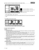
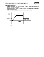
[Burnout]
When the thermocouple or RTD input is burnt out, OUT1 is turned off (for control output Analogue
current signal (4 ... 20 mA), OUT1 low limit value) and the PV display blinks “
”.
[Self-diagnosis]
The CPU is monitored by a watchdog timer, and when any abnormal status is found on the CPU,
the controller is switched to warm-up status.
[Automatic cold junction temperature compensation]
(Thermocouple input type)
This detects the temperature at the connecting terminal between thermocouple and the instrument,
and always keeps it on the same status as when the reference junction is located at 0 °C [32 °F].
[Power failure countermeasure]
The setting data is backed up in non-volatile IC memory.
[Warm-up indication]
With thermocouple and RTD inputs, for approx. 3 seconds after the power is switched ON, sensor
input character and temperature unit are indicated on the PV display, and the input range high limit
value is indicated on the SV display.
With the DC input, for approx. 3 seconds after the power is switched ON, sensor input character is
indicated on the PV display, and scaling high limit value is indicated on the SV display.
(However, if the scaling high limit value has been changed in the Scaling high limit setting, the
changed value will be indicated on the SV display.)
[Auto/Manual control switching]
If Auto/Manual control function is selected during
OUT
/
OFF
key function selection, automatic control
can be switched to manual control or vice versa by pressing the
OUT
/
OFF
key.
When the control action is changed from automatic to manual control and vice versa, the bal-
anceless-bumpless function works to prevent sudden change of manipulated variable.
When the control action is changed from automatic to manual control, the 1
st
decimal point from
the right on the SV display blinks.
The manipulated variable (MV) on the SV display can be increased or decreased by pressing the
▲
or
▼
keys and the control is performed. (When the power supply to the instrument is turned on,
automatic control starts)
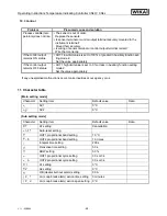
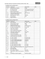
Accessories
: Instruction manual
1 copy
Screw type mounting bracket 1 set
CT (current transformer)
CTL-6S
1 piece [when option W10/W11/W12 is added]
CTL-12-S36-10L1 1 piece [when option W15 is added]
Terminal
cover
CS4H
1 piece (when the option KAB is added)
CS4L
2 pieces (when the option KAB is added)


