background image

Snow Master Vario Flex 3370 
3  Safety notes 


20 

3370 99 01 – 003 

02 | 2019 

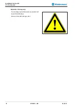
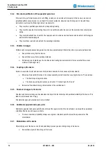
Hazard due to welding work 

Welding should only be carried out by persons with a relevant 
qualifying certificate i.a.w. EN287. 

Improper welding work jeopardises the operational reliability of 
the machine. This can then lead to a risk of serious or even fatal 
injuries. 


Never weld any of the following parts: 


Components of the hydraulic system 


Chassis or load bearing assemblies 


Prior to performing welding work on the device, shut 
down the device securely and uncouple it from the 
tractor. 


Attach the earth of the welding device near to the 
welding point. 


Avoid generation of toxic vapour and dust. 
Hazardous fumes can be produced when paint is 
heated by welding, soldering, or using a torch. 


Do all work outside or in a well ventilated area.  


Dispose of paint and solvent properly. 


Remove paint before welding or heating: 


If you sand or grind paint, avoid breathing the 
dust. Wear an approved respirator. 


If you use solvent or paint stripper with soap and 
water before welding. Remove solvent or paint 
stripper containers and other flammable material 
from the area. Allow fumes to disperse at least 
15 minutes before welding or heating. 

3.7.


Safety routines 

3.7.1.


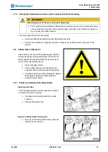
Shutting down and securing the device 


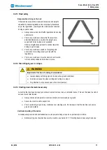
WARNING!


Risk of injury due to movements of the device or device parts! 


Shut down and secure the device before leaving the operator's seat! 

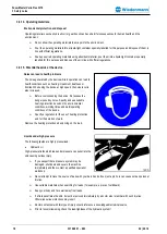
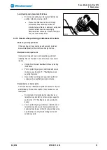
To shut down and secure the device: 


Shut down the tractor's engine, remove the ignition key and take it with you. 


Secure the tractor to prevent it from rolling away. (parking brake). 


Содержание SNOW MASTER VARIO FLEX 3370 Series

Страница 1: ...Translation of original Operating Instruction EN Snow Rake Blade Snow Master Vario Flex Series 3370 Document number 3370 99 01 003 From equioment I D No Status 02 2019...

Страница 2: ...g and observe the safety information Keep these operating instructions in a safe place 1 Manufacturer Wiedenmann GmbH Tel 49 7345 953 0 Am Bahnhof Fax 49 7345 953 233 89192 Rammingen info wiedenmann d...

Страница 3: ...nds to the state of the art of the time when these operating instructions were created Before delivery of this machine your dealer performed a pre delivery inspection to ensure optimal performance In...

Страница 4: ...es 12 3 1 Obligation of the operator 12 3 2 Obligation of the operator 12 3 3 Intended use 12 3 4 Foreseeable incorect use 12 3 5 Service life of the device 13 3 6 General safety instructions 13 3 6 1...

Страница 5: ...3370 28 4 3 2 Technical data sheet 02 type 3370 29 4 3 3 Torques for metric screws 30 5 Assembly 31 5 1 General information on assembly 31 5 2 Mounting the scraping edges 31 5 2 1 Plastic cutting edge...

Страница 6: ...ol Unit Vario Flex electro hydraulic 42 8 3 1 Overview control unit Vario Flex 42 8 3 2 Switch on the control unit Vario Flex 42 8 3 3 Operating the inner shields 43 8 3 4 Operating the outer shields...

Страница 7: ...strips 59 11 7 1 Plastic cutting edges 59 11 7 2 Steel scraping edges 60 11 7 3 Secure corundum plastic scraping edges 60 11 7 4 Scraper block 60 11 8 Skid shoes 60 11 8 1 Fitting a new skid shoe 60...

Страница 8: ...ating instructions the following documents are also supplied and should also be observed Operating manual tractor 2 4 Target group of the document This document is aimed at machine operators that fulf...

Страница 9: ...rformed one step at a time This symbol represents a prerequisite that must be met in order to perform an action step or sequence of actions This arrow represents the interim result of an action step T...

Страница 10: ...Flex 3370 2 To this document 10 3370 99 01 003 02 2019 Explanation of the danger sign This is the danger symbol that warns about a potential risk of injury and material damage Observe all notes with...

Страница 11: ...rning message is not observed CAUTION The signal word CAUTION warns of a dangerous situation that could lead to minor or moderate injuries if the warning message is not observed ATTENTION The signal w...

Страница 12: ...sections of the operating instructions that are important for performing the work assigned to them If the operator determines that a safety device is not in perfect working order this defect must be...

Страница 13: ...le loads and axle load distribution The tractor s ability to steer and brake must be maintained The driving and operating properties of the tractor may be influenced by the attachment of the device Al...

Страница 14: ...ne and activating device movements first ensure that there are no children in the danger area 3 6 4 Coupling up the device Failure to couple the tractor and device correctly leads to hazards that can...

Страница 15: ...onal reliability and cause accidents This can then lead to a risk of serious or even fatal injuries The following parts of the device are particularly important with regards to safety Guards Coupling...

Страница 16: ...ds Keep hands feet and garments well away from moving parts Before starting up the device re attach any guards covering device parts that were removed and then move them into their guard position If y...

Страница 17: ...heir neutral position and lock them in place 3 6 12 Risk of tipping over on slopes WARNING Impairment of the tractor s driving characteristics Always adapt your driving style to the respective ground...

Страница 18: ...danger posed by noise Specify and use suitable hearing protection based on the environmental conditions working times and work operating conditions of the device Specify a regulation for the use of he...

Страница 19: ...operational reliability This can then lead to a risk of serious or even fatal injuries Only perform the work described in these operating instructions Prior to performing any work shut down and secure...

Страница 20: ...produced when paint is heated by welding soldering or using a torch Do all work outside or in a well ventilated area Dispose of paint and solvent properly Remove paint before welding or heating If yo...

Страница 21: ...Safety mark on the device Safety stickers on the device offer warnings against hazards in danger areas and are an important component of the devices safety equipment Missing safety stickers increase t...

Страница 22: ...Snow Master Vario Flex 3370 3 Safety notes 22 3370 99 01 003 02 2019 Danger of crushing stay clear of swivel area When the tractor engine is running stay clear of the swivel area of the rake blade...

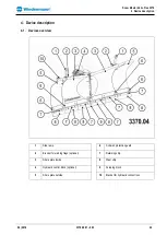
Страница 23: ...vice description 4 1 Devices overview 1 Side lamp 6 Collision protection guard 2 Bracket for warning flags optional 7 Retaining strip 3 Share plate inside 8 Waer strip 4 Hydraulic control block option...

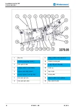
Страница 24: ...on protection guard 3 Share plate left inside 11 6x wear strips with spring flaps 4 Hydraulic cylinder for outer left blade 12 Skid shoes 5 Hydraulic control block optional 13 Support plate 6 Hydrauli...

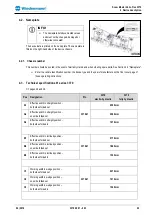
Страница 25: ...structions 4 3 Technical specifications 01 series 3370 Cf pages 28 and 29 Pos Designation Pic 3370 electro hydraulic 3370 fully hydraulic A1 Effective width in straight position both sides folded out...

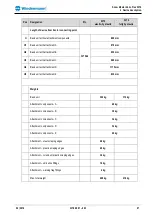
Страница 26: ...side folded out 2125 mm E3 Width of device both sides folded in 1710 mm Working speed at full weight loads on skide shoes 20 km h Working speed at full weight loads on wear strips 16 km h Attachment t...

Страница 27: ...sic unit with attachment C 900 mm H4 Basic unit with attachment D 1115 mm H5 Basic unit with attachment E 830 mm Weights Basic unit 322 kg 312 kg Attachment components A 20 kg Attachment components B...

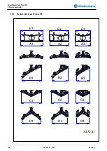
Страница 28: ...Snow Master Vario Flex 3370 4 Device description 28 3370 99 01 003 02 2019 4 3 1 Technical data sheet 01 type 3370 3370 41 E1 A1 A2 A3 E2 E3 B1 B2 B3 C1 C2 C3 D1 D2 D3...

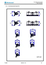
Страница 29: ...Snow Master Vario Flex 3370 4 Device description 02 2019 3370 99 01 003 29 4 3 2 Technical data sheet 02 type 3370 3370 42 G F F1 F2 G2 G1 H H H H H H1 H3 H5 H4 H2...

Страница 30: ...1150 2000 1500 M30 675 490 850 625 1300 950 1650 1200 1850 1350 2300 1700 2150 1600 2700 2000 M33 900 675 1150 850 1750 1300 2200 1650 2500 1850 3150 2350 2900 2150 3700 2750 M36 1150 850 1450 1075 22...

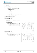
Страница 31: ...during operation 5 2 Mounting the scraping edges 5 2 1 Plastic cutting edges Plastic scraping edges are easy going on the road surface and are not as noisy Fitting new wear strips Fit new wear strips...

Страница 32: ...nuts 5 2 4 Scraper block Fitting a new scraper block Insert a new scraper block 1 into the bracket and secure with a hexagon socket screw 5 3 Mounting the skid shoes Screw skid shoe 1 into hole patter...

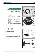
Страница 33: ...A at position F Insert flat connector G of green yellow line in socket A at position H Connect ring shoe of lines 1 and 2 to positive terminal of battery Connect ring shoe of green yellow line to nega...

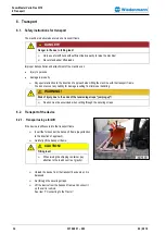
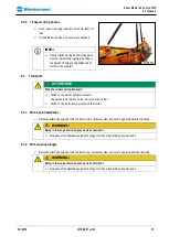
Страница 34: ...lity for damage resulting from improper handling WARNING Risk of injury due to the ends of the tensioning straps jumping up Caution must be excercised when cutting through the securing straps 6 2 Tran...

Страница 35: ...3 2 Switch on the control unit Vario Flex Switch on the road travel protection on the tractor 6 3 1 With 3 point installation Raise the attached equipment with the tractor rear hydraulic system and se...

Страница 36: ...trestle The attachment components must be attached to the rake blade so that the lower guide bar of the tractor front hydraulic system are parallel to the ground or just slightly tilted downward INFO...

Страница 37: ...t hydraulic system so that the triangular coupling 1 engages Adjust safety catch 2 Raise parking supports See section 7 6 Raising the support Connect hydraulic lines See section 7 7 Connecting the hyd...

Страница 38: ...bends and chafing of the hydraulic lines Secure the hydraulic connections 1 2 to the hydraulic sockets located on the front of the tractor Connections A and B Connect the optional depressurised return...

Страница 39: ...3 39 Connect the following hydraulic connections on the tractor Hydraulic connections green 1 and 2 Inner shield left Hydraulic connections red 3 and 4 Inner shield right Hydraulic connections yellow...

Страница 40: ...rve generally applicable safety and accident prevention standards During operation on public highways the relevant traffic regulations must be observed Ensure the permissible front axle load is not ex...

Страница 41: ...constantly approx 6 mm from top to bottom Adjust the distance between the middle and outer shields as required by turning the adjusting bolt 2 Turn the cylinder eyelet 3 on the piston rod 4 until the...

Страница 42: ...LED for left shield position 5 Selection button for right outer shield 2 Unlock button 6 Selection button for inner shields 3 Control LED for right shield position 7 Selection button for left outer s...

Страница 43: ...that they are pointing in the same direction forwards back 180 function yellow The 180 function is active as soon as the yellow LED flashes This moves the shield as a straight shield Both sides of the...

Страница 44: ...2 light up red Selecting the left outer shield Press the selection button 4 Selecting the right outer shield Press the selection button 3 Selecting the left and right outer shields at the same time P...

Страница 45: ...iate danger of collision with the attachment the shield function will be disabled The corresponding LED 1 or 2 flashes red To reset the shield using the unlock function see Section 8 3 6 Meaning of th...

Страница 46: ...again The Garage access special function is ended and the control system switches back to the previous function 8 3 6 Meaning of the left and right warning LEDs Left LED 2 Lights up green Shield is a...

Страница 47: ...he vehicle hydraulics In this case the outer shield can only be moved forwards If the shield is moved backwards towards the attachment the hydraulic valve stops the movement for 2 sec Afterwards the s...

Страница 48: ...the selection button 6 Left garage function Press the selection buttons 6 and 4 Right garage function Press the selection buttons 6 and 5 Ending the emergency function Press the unlock button 3 again...

Страница 49: ...ulic system of the tractor must always be in the floating position during operation After a short running in period check the security of all screw fittings Check the parts connecting the equipment to...

Страница 50: ...rake Always position the machine on a flat surface before detaching it WARNING Failure to wear personal protective equipment poses a risk of injury Wear personal protective equipment See Section 3 6 1...

Страница 51: ...efully back out 10 5 Removal with triangular coupling B Lower the supports Release safety catch 2 Disconnect hydraulic lines Lower the snow rake blade to the ground and carefully back out 10 6 Removal...

Страница 52: ...t it from rolling away parking brake WARNING Failure to wear personal protective equipment poses a risk of injury Wear personal protective equipment See Section 3 6 10 Personal protective equipment AT...

Страница 53: ...heck the collision protection guard for wear Repair worn wear protection Guide bushings Check bearing play Readjust the play by adjusting the hydraulic cylinder eye on the piston rod or replace the se...

Страница 54: ...shields on both sides Central pivot point Lubricate the grease nipple 1 of the central pivot point Adjustment pivot point Lubricate the grease nipple 1 of the adjustment pivot point 11 4 Hydraulic sy...

Страница 55: ...uid penetrates the skin it must be removed immediately by a doctor who is familiar with such injuries Otherwise serious infections may result Doctors unfamiliar with this type of injury should referen...

Страница 56: ...ween hydraulic cylinder and control block A2 3 Connection between hydraulic cylinder and T union 4 Hydraulic cylinder for right inner shield 5 T union 6 Connection between T union and control block B...

Страница 57: ...ght outer shield yellow 1 Stroke limiter 2 Connection between stroke limiter and pressure relief valve 3 Pressure relief valve Hydraulic cylinder for right outer shield 4 Hydraulic cylinder for left o...

Страница 58: ...between tractor and pressure relief valve 5 Hydraulic connection green between tractor and hydraulic cylinder for inner shield Hydraulic connection for pressureless return line blue 1 Pressure relief...

Страница 59: ...on caused by dripping oil Bind drops of oil with a binding agent and dispose of it according to the regulations Eliminate the cause WARNING Failure to wear personal protective equipment poses a risk o...

Страница 60: ...strips 1 in hole row A and secure them in place with countersunk screws washers and self locking nuts 11 7 4 Scraper block Fitting a new scraper block Insert a new scraper block 1 into the bracket and...

Страница 61: ...11 9 Unauthorized conversion and spare part manufacture Only convert or change the machine with the express permission of the manufacturer The use of original parts and accessories authorized by the...

Страница 62: ...on trestle mounted incorrectly Check the position of the installation trestle and change if necessary see Section 7 2 The correct position of the installation trestle Rake shield is rattling severely...

Страница 63: ...ection 8 3 7 Unlock button function Vario Flex no longer works Function button on control unit and LED lit up red on the electrohydraulic model Angle sensor faulty 1 4 Left outer shield 2 3 Right oute...

Страница 64: ...t in a suitable vessel Disassemble the machine from top to bottom ATTENTION Incorrect disposal of environmentally hazardous substances Regulations and laws concerning the disposal of hazardous substan...

Страница 65: ...ario Flex 3370 14 Additional Equipment 02 2019 3370 99 01 003 65 14 2 Additional equipment 14 3 1 Standard attachment components Model A A frame cat 0 Model B triangular coupling Model C three point h...

Страница 66: ...019 14 3 1 Special attachment components Model G for Holder Multipack tractors Model E for Tremo 14 3 Tine set 3370 electro hydraulic 3370 fully hydraulic Steel scraping edge W W Plastic scraping edge...

Страница 67: ...14 Additional Equipment 02 2019 3370 99 01 003 67 14 4 Special equipment 3370 electro hydraulic 3370 fully hydraulic Gliding show fittings O O Warning flag fittings O O Side lamp fittings S S S stand...

Страница 68: ...th the relevant basic safety and health requirements of the machinery directive 2006 42 EC Rammingen the 09 10 2018 Horst Wiedenmann Place and date of issue Managing Partner Name function and signatur...

Страница 69: ...duct Snow Rake Blade Snow Master Vario Flex Series 3370 referred to by this declaration complies with the requirements of Machinery Directive 2006 42 EC Rammingen the 09 10 2018 Oliver Matthes Place a...

Страница 70: ...Snow Master Vario Flex 3370 17 Notes 70 3370 99 01 003 02 2019 17 Notes...

Страница 71: ...Snow Master Vario Flex 3370 17 Notes 02 2019 3370 99 01 003 71...

Отзывы: