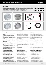


InstallatIon · Manual
Installing the spotlight
Guide the UW cable through the inside cable fitting of the installation
housing and into the cable protection conduit and wrap approx. 1.5 m of
cable inside the installation housing. Tighten the cable fitting firmly to seal
the cable.
3.10.
Insert the spotlight, align and tighten it. If the installation housing is
installed with incorrect orientation, a compensating adapter ring must be
planned for as an option (on request)
Screw the accompanying M20 plastic fitting onto the plastic end piece and
tighten the lock nut so that the cable is sealed.
3.8.
attention:
Use only cable connected at the factory. Specify desired
cable length when ordering.
Connect individual wires to the power supply according to the regulations.
3.9.
For the maximum number of lights and connection type, also see the
manual of the corresponding power supply unit or RGB(W) controllers.
note:
If the cable is not connected at the factory, see point 4.
4. Cable connection, sealing compound
and maintenance
If the cable was not connected and sealed at the factory, guide the UW
cable through the inside cable fitting of the installation housing and into
the cable protection conduit and wrap approx. 1.5 m of cable inside the in-
stallation housing. Tighten the cable fitting firmly to seal the cable.
3.10.
Open the connection unit on the back of the spotlight, guide the cable
through the cable fitting on the spotlight, connect it accordingly to the
connection terminals, screw on the tension relief, seal the cable fitting
and seal the complete connection unit with sealing compound. After that,
screw the cover with seal back on tight.
3.11.
note:
Sealing compound 9.9011.00.25 sufficient for 2 spotlights. Please
order separately.
Install spotlight as described above.
Soiling and deposits on glass or stainless steel parts must be removed with
standard cleaning agents.
Montage du projecteur
Rentrer le câble UW par le presse-étoupe du boîtier d‘encastrement dans
la gaine de protection du câble et enrouler environ 1,5 m de câble dans le
boîtier d‘encastrement. Bloquer le presse-étoupe pour étanchéifier le câble.
3.10.
Insérer, ajuster et fixer le projecteur. En cas de montage mal aligné du boîtier
d‘encastrement, il faut prévoir une bague d‘adaptation d‘équilibrage en
option (sur demande).
Visser le raccord à vis M20 en plastique fourni au niveau de l‘embout
d‘extrémité en plastique et serrer l‘écrou-raccord afin d‘étanchéifier le câble.
3.8.
attention:
utiliser uniquement les câbles raccordés en usine. Indiquer
la longueur de câble souhaitée lors de la commande.
Raccorder les différents conducteurs aux blocs d‘alimentation conformément
aux prescriptions.
3.9.
Pour le nombre maximal d‘ampoules et le type de raccordement, voir aussi le
manuel du bloc d‘alimentation concerné ou les contrôleurs RVB(B).
Remarque:
Si le câble n‘a pas été raccordé en usine, voir le point 4.
4. Raccordement du câble,
scellement et maintenance
CRentrer le câble UW à travers le presse-étoupe intérieur du boîtier
d‘encastrement dans la gaine du câble et enrouler environ 1,5 m de câble
du boîtier d‘encastrement dans la gaine de protection du câble . Bloquer le
presse-étoupe pour étanchéifier le câble.
3.10.
Ouvrir l‘unité de raccordement au dos du projecteur, amener le câble jusqu‘au
projecteur à travers le presse-étoupe, le raccorder en conséquence aux bornes
de branchement du projecteur, visser la pince de décharge de traction, fermer
le presse-étoupe et sceller toute l‘unité de raccordement avec le masse de
scellement. Revisser ensuite le couvercle à bloc avec le joint.
3.11.
Remarque:
Masse de scellement 9.9011.00.25 suffisant pour
2 projecteurs. A commander séparément.
Monter le projecteur comme décrit plus haut.
Les impuretés et les dépôts sur le verre ou les pièces en acier inoxydable
doivent être éliminés à l‘aide d‘un détergent classique.
WIBRE Elektrogeräte Edmund Breuninger GmbH & Co. KG · Liebigstrasse 9 · 74211 Leingarten/Germany
Telefon: +49 (0) 7131 9053-0 · Telefax: +49 (0) 7131 9053-19 · E-Mail: [email protected]
4
/6
Montage des scheinwerfers
Das UW-Kabel durch die innenliegende Kabelverschraubung des Ein-
baugehäuses in das Kabelschutzrohr einführen und ca. 1,5 m Kabel
im Einbaugehäuse einwickeln. Die Kabelverschraubung festziehen,
damit das Kabel abgedichtet wird.
3.10.
Den Scheinwerfer einsetzen, ausrichten und festschrauben. Bei
falsch ausgerichtetem Einbau des Einbaugehäuses muss ein Aus-
gleichsadapterring optional vorgesehen werden (auf Anfrage)
Am Kunststoffabschlussstück beiliegende Kunststoffverschraubung
M20 einschrauben und Überwurfmutter festziehen, damit das Kabel
abgedichtet wird.
3.8.
achtung:
Nur werkseitig angeschlossenes Kabel verwenden.
Gewünschte Kabellänge bei Bestellung angeben.
Einzelanschlussader entsprechend den Vorschriften an den Netztei-
len elektrisch anschließen.
3.9.
Die maximale Anzahl von Leuchten und Anschlußart siehe auch
Manual des entsprechenden Netzteiles oder RGB(W) Controlers.
Hinweis:
Bei nicht werkseitig angeschlossenem Kabel siehe
Punkt 4.
4. Kabelanschluß, Verguß und Wartung
Bei nicht werksseitig angeschlossenem und vergossenem Kabel, das
UW-Kabel durch die innenliegende Kabelverschraubung des Einbau-
gehäuses in das Kabelschutzrohr einführen und ca. 1,5 m Kabel im
Einbaugehäuse belassen. Die Kabelverschraubung festziehen, damit
das Kabel abgedichtet wird.
3.10.
Am Scheinwerfer rückseitig den Anschlußeinheit öffnen. das Kabel
durch die Kabelverschraubung am Scheinwerfer einführen, entspre-
chend an den Anschlussklemmen am Scheinwerfer anschließen,
Zugentlastung anschrauben, die Kabelverschraubung verschließen
und die komplette Anschlusseinheit mit Vergußmasse vergießen.
Danach den Deckel mit Dichtung wieder fest verschrauben.
3.11.
Hinweis:
Vergußmasse 9.9011.00.25 ausreichend für 2 Schein-
werfer. Bitte separat bestellen.
Scheinwerfer wie oben beschrieben einbauen.
Verunreinigungen und Ablagerungen auf Glas oder Edelstahlteilen
sind mit handelsüblichen Reinigungsmitteln zu entfernen.
max 40 m
5.0670.12.72
prim
230 V
dimm
dimm
1
2
3.9
Deckel
Cover
Couvercle
Schraube
Screw
Vis
Verguß
Sealing
Scellement
Anschlußeinheit
Connection Unity
Raccordement
Zugentlastung
Cable anchorage
Décharge de traction
Dichteinsatz
Seal insert
Joint
Überwurfmutter
Cap nut
Écrou
– +
Dichtung
Seal
Joint
Auffüllen Vergußhöhe
Height of filling
Niveau de scellement
M
ischb
eut
el
M
ixing bag
sac mélangeur
3.11
achtung:
Anschluss der Netzteile muss stromlos erfolgen,
da sonst Entladungen im Netzteil zur Schädigung der LED führen
können. Es darf keine Primärspannung anliegen.
achtung:
Werden weniger als 4 Scheinwerfer angeschlossen, ist
die Reihenfolge der Ausgangskanäle zu beachten, beim Anschluss
von nur 3 Scheinwerfern werden also die Kanäle 1 bis 3 benutzt, bei
2 Scheinwerfern die Kanäle 1 bis 2 und so weiter.
Hinweis:
Die Installation eines bauseitigen Überspannungsschutzes
nach DIN VDE 0100-443, DIN VDE 0100-534 und EN 62305 wird empfohlen.
attention:
The power supply must be connected without power,
since otherwise discharges in the power supply unit may damage
the LED. Primary voltage must not be present.
attention:
If less than 4 spotlights are connected, the sequence
of the output channels must be observed; if only 3 spotlights are
connected, channels 1 to 3 are used, if 2 spotlights are connected
channels 1 to 2 are used, and so on.
note:
Installation of customised surge protection in accordance with
DIN VDE 0100-443, DIN VDE 0100-534 and EN 62305 is recommended.
attention:
Les blocs d‘alimentation doivent être raccordés hors ten-
sion, sinon des décharges dans le bloc d‘alimentation peuvent détériorer
les LED. Aucune tension primaire ne doit être présente.
attention:
Si on raccorde moins de 4 projecteurs, il faut suivre l‘ordre
des canaux de sortie. Si on raccorde seulement 3 projecteurs, on utilise par
conséquent les canaux 1 à 3, 2 projecteurs les canaux 1 à 2 et ainsi de suite.
Remarque:
L‘installation d‘un système anti-surtension local
conforme aux normes DIN VDE 0100-443, DIN VDE 0100-534 et EN 62305
est recommandée.
achtung:
Ein Montageabstand von 10 cm zwischen Betriebs-
geräten wird dringend empfohlen, um wechselseitiges Erhitzen zu
vermeiden.
Hinweis:
Nur Edelstahlwerkzeug verwenden!
Zur Vermeidung von Fremdrost!
attention:
A mounting distance of 10 cm between various
power supplies is strongly recommended, in order to avoid mutual
heating.
note:
Only use tools made of stainless steel!
To avoid extraneous rust!
attention:
Une distance de montage de 10 cm entre plusieurs
alimentations est vivement conseillé pour éviter une chauffe
mutuelle !
Remarque:
L‘utilisation d‘outils en acier inoxydable est obliga-
toire! Pour éviter que la corrosion se forme!


