


5200AFGMS Ambierle Sofa
Table
Assembly Instructions
5200AFGMS
— Page 5 — 03/14
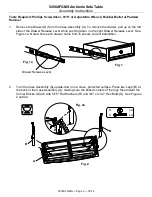
5.
Attach the legs to the Case Assembly with 5/16" Flat Washers (R) and 3/8" x 2-1/2" Hex Bolts
(S). See Figures 5 and 5a.
6.
Turn the unit onto its top and using the pocket holes as guides, secure the Shelf Assembly (C)
to the Legs (B) with four #8 x 1-1/4" Pan Head Screws (J). See Figures 6 and 6a.
Fig. 5
Fig. 5a
R
S
x 4
x 4
S
R
Fig. 6
J
x 4
J
Fig. 6a


