Whittier Wood 3510GAC Скачать руководство пользователя страница 5

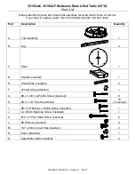
3510GAC 3510CAF McKenzie Round End Table (26"D) 

Assembly Instructions


3510GAC_3510CAF — Page 5 — 08/17 
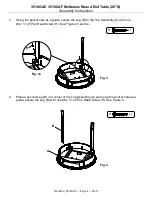
 
5. 

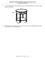
Place a third Leg (B) in a  corner of the Top Assembly (A) and using the pocket hole as a guide, 
secure the Leg (B) with one #8 x 1-1/4" Pan Head Screw (H). See Figure 5. 
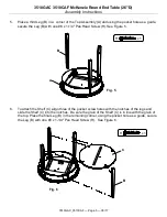


6. 

To attach the Shelf (C) align three of the pocket screw holes with the notches of the legs and 
slide the Shelf (C) into the notches.  Be sure the grain of the Shelf (C) is in line with the grain of 
the top. Place the final Leg (B) in the remaining corner, using the pocket hole as a guide, secure 
the Leg (B) with one #8 x 1-1/4" Pan Head Screw (H).  See Figure 6. 


Fig. 6 

x 1 

Fig. 5 

x 1 

Содержание 3510GAC

Страница 1: ...luding formaldehyde which are known to the State of California to cause cancer For more information go to www p65warnings ca gov furniture DESIGN SUBJECT TO CHANGE WITHOUT NOTICE CUSTOMER SERVICE If you ever have questions about your furniture please do not hesitate to contact us In the unlikely event you need a replacement part we can make those parts available through an authorized Whittier Wood...

Страница 2: ...t name Part Description Quantity A Top Assembly 1 B Leg 4 C Shelf 1 D Drawer inserted 1 E Wood Slide installed 2 F Drawer Stop attached 1 G 8 x 1 3 8 Lo Profile Screw inserted 9 H 8 x 1 1 4 Pan Head Screw 19 7 inserted I 8 x 7 8 Black Lo Profile Screw inserted 1 J 4 x 25mm Machine Screw installed 1 K 10 x 2 Pan Head Screw inserted 6 L 8 Washer inserted 9 M 1 4 x 20mm Insert Nut inserted 4 N Knob a...

Страница 3: ...et or Padded Hammer 1 Turn the Top Assembly A upside down on a clean protected surface Position the Drawer Stop F so that it is unlocked remove the Drawer D and place it off to the side See Figures1 1a and 1b 2 Place a Leg B in a corner of the Top Assembly A See Figure 2 Fig 2 B A Fig 1 Fig 1a A Locked Position Unlocked Position Fig 1b F D F F ...

Страница 4: ...cket hole as a guide secure the Leg B to the Top Assembly A with one 8 x 1 1 4 Pan Head Screw H See Figures 3 and 3a 4 Place a second Leg B in a corner of the Top Assembly A and using the pocket hole as a guide secure the Leg B with one 8 x 1 1 4 Pan Head Screw H See Figure 4 Fig 4 B A H x 1 Fig 3 H x 1 Fig 3a H ...

Страница 5: ... 8 x 1 1 4 Pan Head Screw H See Figure 5 6 To attach the Shelf C align three of the pocket screw holes with the notches of the legs and slide the Shelf C into the notches Be sure the grain of the Shelf C is in line with the grain of the top Place the final Leg B in the remaining corner using the pocket hole as a guide secure the Leg B with one 8 x 1 1 4 Pan Head Screw H See Figure 6 Fig 6 B C H x ...

Страница 6: ...7 Using the pocket holes as guides secure the Shelf C to the Legs B with four 8 x 1 1 4 Pan Head Screws H See Figures 7 and 7a 8 Using the pocket holes as guides secure the side aprons to the Legs B with four 8 x 1 1 4 Pan Head Screws H See Figures 8 and 8a Fig 8 H x 4 H Fig 8a Fig 7 H x 4 H Fig 7a ...

Страница 7: ...CAF Page 7 08 17 9 Turn the table upright and insert the Drawer D Rotate the Drawer Stop F back to the locked position See Figure 9 10 Place the table at its final destination To level the table rotate the Adjustable Glides O found on the bottoms of the legs See Figure 9 Fig 9 O O ...

Отзывы: