


1131GACg 1131CAFg 8-Drawer McKenzie Dresser
Assembly Instructions
1131GACg_1131CAFg
— Page 7 — 07/18
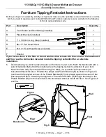
Furniture Tipping Restraint Instructions
Before you begin this assembly, identify each part and make sure the quantities received match what is on this
list. If you need to replace a part, contact Whittier Wood Furniture customer service and refer to the following
list for its name and letter code.
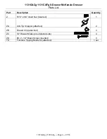
Part
Description
Quantity
A
Cam Buckle and Short Strap (installed)
1
B
Plastic Bracket (installed)
1
C
1" x 1000mm Long Strap (installed)
1
D
#8 x 3" Pan Head Screw
2
E
#10 x 1" Oval Head Screw (inserted)
1
F
Washer
1
If you have a stone or tile floor or do not wish to drive screws into the corner of the baseboard
and floor see the instruction included inside the tipping restraint kit for an alternate
installation.
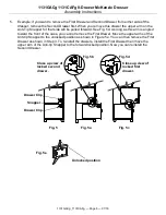
6.
Decide where you want to place the piece of furniture in your room. Mark the baseboard with a
pencil mark directly behind the location where the tipping restraint is attached to your item.
Move the item away from the wall far enough to allow you to access the spot where the
baseboard meets the floor. Position the straps and Plastic Bracket (B) as shown in Figures 6
and 6a with the angled corners of the Plastic Bracket (B) firmly placed against the seam of the
baseboard and floor. Attach by driving #8 x 3" Pan Head Screws (D) through the holes in the
Plastic Bracket (B) into the seam below the baseboard where it meets the floor. See Figures 6
and 6a.
Wall
Fig. 6
D
x 2
Fig. 6a
Floor
D
Floor
Baseboard


