Whitmore LUBRICURVE ELECTRO 10 Скачать руководство пользователя страница 29

29 


10.3


Blade System 

The system allows use of a range of grease distribution units (blades): 


Running Rail Blades 

o


2 blades on high rail. 

o


4 blades on the high rail and 4 blades on the low rail. 

There are two styles of Blade available; standard (reference Section 10.4, 10.5 below) and EasiBlade. 
Each is available in 40 or 60cm lengths. 

10.4


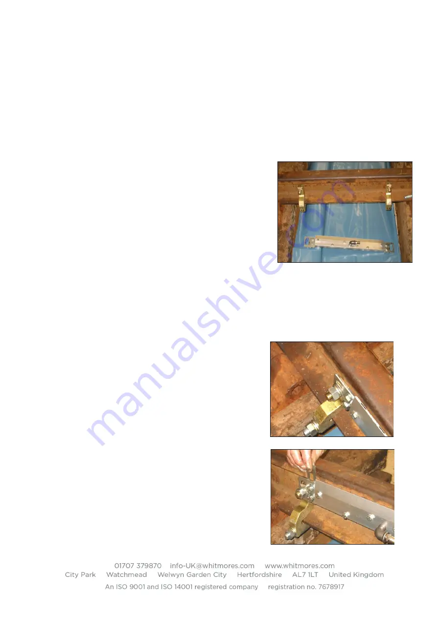
Installing the Blade Rail Clamps (Standard Style) 

10.4.1


Once the position of the Blade to be fitted has 
been identified, lay the Blade unit adjacent to the 
rail (on the “4 foot” side) in order to locate where 
the Blade clamps need to be fitted. 

10.4.2


Both Blade clamps can now be fitted (image on the 
right). 

10.4.3


The main part of the clamp is fitted on the “4 foot” 
side of the rail with the threaded stud at the top 
and facing away from the rail. 

10.4.4


The hook bolt is then fitted under the rail with the hook clasping the foot of the rail on the 
field side with the threaded part inserted through the hole at the base of the clamp. 

10.4.5


The washers and nyloc nut are then to be fitted to the hook bolt and fastened tight. 

10.4.6


Repeat for the second clamp. 

10.5


Installing the Blades (Standard Style) 

10.5.1


Fit the Blade onto the clamps using the M16 flat 
washer, spring washer and nut onto each clamp 
and secure. Hold the blade against the gauge 
face of the rail, if there is a gap between the back 
plate and the gauge face of the rail spacing shims 
will need to be fitted. 

10.5.2


To fit the spacing shims loosen the two M10 
bolts that fit the Blade plates to the brackets.  
Slip the number of shims needed behind the 
plate and over the threads of the M10 bolts 
between the bracket and the blade backplane. 

10.5.3


Repeat for the other end of the blade if 
necessary. 

10.5.4


Once again fit the blade onto the clamps and 
hold the blade against the gauge face of the rail. 

10.5.5


If there is no gap, fit the M16 flat washer and 
nyloc nut onto each clamp and tighten lightly so 
the blade can still be moved. 


Содержание LUBRICURVE ELECTRO 10

Страница 1: ...URVE ELECTRO 10 20 30 Installation Maintenance Manual TRACKSIDE ELECTRIC RAIL WHEEL LUBRICATOR SYSTEM Model Variants Solar Mast Solar Cabinet Solar Wind Mains Battery Control box MK3 90Kg 200Kg 400kg Capacity ...

Страница 2: ...e electrolyte may cause severe burns If the electrolyte contacts the skin wash with large quantities of clean water and seek medical advice DO NOT expose the battery to naked flames or cigarettes During the charging process hydrogen gasses are vented from the battery and these gasses when mixed with the air may explode if ignited Do not short circuit the battery terminals as this may cause a spark...

Страница 3: ...ems 20 8 14 Solar Systems Mast Mounted 21 8 15 Solar Systems Cabinet Mounted Panels 21 8 16 Mains Powered Systems 22 8 17 Battery Powered Systems 24 8 18 Replacing the Pump Sensor 24 9 System Wiring Diagram 25 10 Installation of Track Items 26 10 1 Wheel sensor 26 10 2 Wheel sensor Single Direction Operation 27 10 3 Blade System 29 10 4 Installing the Blade Rail Clamps Standard Style 29 10 5 Insta...

Страница 4: ...3 12 8 Checking for Leaks 43 12 9 Measuring Testing the Wheel sensor 44 12 10 Adjusting Replacing Pump Sensor 44 12 11 Checking for Airlocks 45 12 12 Inspection of the Blade s 45 12 13 Filling the Reservoir 46 12 14 Maintenance Frequency 46 12 15 Periodic Replacement of Components 46 12 16 Maintenance Log Sheet Example 47 13 Parts List 48 14 Basic Installation Tool Kit 48 ...

Страница 5: ... the rail user can be used in these LubriCurve Electro systems Use of other greases will invalidate warranty and could affect operation 2 Product Transport Storage Goods are packed and delivered to the requested address in a form that is suitable for the product given good practice in the off loading by the receiving company LubriCurve systems are delivered on the basis that they will be installed...

Страница 6: ...d cable Integral Mast Generally integral with the Cabinet the mast provides secure mounting of the solar panel or wind turbine at a high level Various heights and options are available Solar Panel Depending on the model a solar panel is supplied The unit fits onto the mast and is used to provide power to the battery by utilising sun light and ambient light to generate electric power Wind Turbine D...

Страница 7: ...d with reference to the green indicator lamp on the charge controller or the voltmeter display Blade Ensure the blades are not bent or damaged and all ports are free from blockages Ensure that all bolts are present and are fitted securely Ensure that the hose inlet tails which the delivery hoses attach to are in place and are not damaged Clamps Ensure that both Sensor and Blade clamps are not dama...

Страница 8: ...g hole and rotated vertically through 90 degrees to secure Four people are required which should be trained and experienced in mechanical handling To reduce the overall weight the battery and other loose installation items that are shipped within the unit should be carefully removed prior to the lift and handled separately Note The cabinet should be kept vertical at all times Take care to avoid da...

Страница 9: ...he diagram below Recommendation is for two full length 8 6 good quality hardwood Sleepers Ties to be fitted at 900 to the track Where there is insufficient space in the CESS for that arrangement then two alternative options are possible o Two length 6 sleepers can be used in place of the 8 6 standard sleepers at 900 to the track Sleepers must be ballast covered for adequate stability o Two full le...

Страница 10: ... drawings below are applicable to the Electro 10 and Electro 20 systems 640 nom 1240 460 460 150 460 700 nom 800 nom 500 nom Direction of Train Travel View on arrow A A 2897 3810 2150 2000 2100 2438 8 nominal ...

Страница 11: ...o the track Short Sleeper Dug in at 900 to the track 2100 2000 1829 6 nominal 950 overall 700 nom centres 460 460 800 nom 640 nom 500 nom Direction of Train Travel 950 0 2100 2000 950 overall 700 nom centres 460 460 800 nom 640 nom 500 nom Direction of Train Travel ...

Страница 12: ...ent required for the installation work includes the following o All relevant P P E needed to carry out the works safely o Shovel or ballast fork whichever one is the most suitable o Orange pipe to protect delivery hose and sensor cable across 4 and 6 o Spirit level o Compass o Lubricator installation tool kit see Section 14 o Wiring termination tools o Cordless or portable drill and bits 8 Install...

Страница 13: ...door can now be opened 8 2 2 The later units have a single key door lock To open the door the key is inserted into the lock located behind the vertically sliding dirt shield Rotate the key clockwise and pull the key and handle outwards The handle can now be rotated clockwise to open the three point locking bars and then open the door 8 2 3 The door stay at the base of the door should be located in...

Страница 14: ...e lowered to either side of the unit to best suit the site conditions The door should first be closed if lowering in the door end direction 8 5 Option Mast Removal Alternative Lower Mast Orientation 8 5 1 Generally the Cabinet will be installed with the Blade hose connectors towards the Track the door hinged away from the Track and the mast upright to the rear of the unit door hinge side If necess...

Страница 15: ...unting module should be initially clamped to the upper mast section as shown in the picture using the two 48mm U Bolts around the mast tube The height should be set so that the panel is well above head height when fitted 8 7 5 With the panel roughly positioned on the mast it is necessary to fine tune its location and orientation to maximise the effectiveness of the unit Rotate the bracket around t...

Страница 16: ...h blade using the four bolts provided two from each side do not over tighten the fixings 8 8 5 Secure the front cover using the three provided plastic bolts 8 8 6 Feed the extension cable down the Mast Tube and into the Cabinet through the hollow mast pivot tube 8 8 7 Feed the remaining cable and Turbine spigot into the Mast and align the two fixing holes Secure in position using the M10 Button He...

Страница 17: ...ditions as the turbine blades will spin and there is load on the solar panel that can increase the required lifting load 8 9 4 With the Mast vertical open the Cabinet door and fit the two U bolts around the mast and through the locating holes Fit and tighten the four M10 Nyloc nuts on the inside of the cabinet a 17mm AF ratchet spanner is recommended 8 9 5 At the base of the Mast fit eight M12 Nyl...

Страница 18: ... or wind to the turbine applications could be cuttings or where general vegetation obscures the charging systems 8 10 3 Required mast extension items are covered in Whitmore Rail Part No LCS105 03 and parts Proceed with installation stage as per Manual Section 8 4 and 8 6 Slide final mast section into the upper mast and secure with M6 hexagon screws Fit solar or wind panel to extended mast as per ...

Страница 19: ...cable and panel and then drill fix at base of the cover 8 11 2 5 Fit the second panel to one side of the cabinet with the panel as far forward near the door as possible and around 10cm below the top Do not Shorten the length of the standard cable or change its end fittings Stand on the panel Drill additional holes in the panel 8 12 Battery Charger Electrical Connection The majority of the electric...

Страница 20: ...ave been connected during initial assembly to the BAT 1 terminals BAT 2 is not generally used Uncover the solar panel and free the turbine so it can rotate freely The display provides a range of information Press the lower lamp button which will illuminate the display Press the upper scroll button which will scroll through the wind generator output solar panel output and battery condition as requi...

Страница 21: ...emains at a low charge the LED will continue to flash slowly 8 15 Solar Systems Cabinet Mounted Panels With cabinet mounted panels there are minor differences 8 15 1 Each cabinet panel cable is connected to the standard charger section 8 14 via a specialist connector block as shown on the pictures below 8 15 2 Remove the top of the connector block by removing the two pozidrive bolts 8 15 3 The thr...

Страница 22: ... a hazard Cable rating should be 220 110 Volt at 6 Amps minimum Connection should be made on the two pole MCBs to the left of the main Control Box All other power wiring will have been completed during product assembly Connection should only be undertaken with the lubricator installer present 8 16 1 Lubricators supplied after April 2011 will have an auto voltage sensing industrial battery charger ...

Страница 23: ...ttery connection Battery fuses blown Very low battery LED Off Check incoming supply voltages Do not connect the mains supply to the MCB or remove the MCB cover or the battery charger cover unless fully trained and certified electrician The closed charger opens by lifting the left side of the cover against you and pull the cover to the left see picture above The Jumper Block for incoming main power...

Страница 24: ... core grey cable from the terminals and draw clear of the control box through the cable gland see wiring diagram in Section 9 remove any cable ties and pull the cable to the base of the cabinet at the rear 8 18 3 The sensor is secured to the pump body with two M8 nuts 13mm open spanner needed Loosen the outer nut loosen the inner nut and then unscrew the sensor fully from the pump body 8 18 4 The ...

Страница 25: ...25 9 System Wiring Diagram ...

Страница 26: ...single hook bolt to clamp it to the rail Fixing details are described below 10 1 1 Fixed Sensor Sensor rail fixing clamps are similar to the blade rail fixing clamp and fitting is generally covered in Section 10 4 the key differences are o Space the clamps to suit the sensor brackets o Fix one clamp on each side of the sleeper Clamp the sensor to the M16 rail clamp studs with the sensor uppermost ...

Страница 27: ...s indicated 10 1 7 Cable connections are as follows Control Box Wheel sensor Brown ve terminal Brown terminal 1 Black ve terminal Black terminal 3 White S terminal White terminal 4 Care should be taken to ensure connections are made correctly and that the terminals are not over tightened and damaged 10 2 Wheel sensor Single Direction Operation On Bi directional track where the pump operation is re...

Страница 28: ...be drilled for the 4 core cable the gland fitted and cable to be passed through Wiring the Terminal Box Prepare the Cable ends of both the 3 and 4 core cables and insert through the cable glands in the Terminal Box The 3 core cable goes through the Right hand Cable gland The 4 core cable goes through the Left hand Cable gland A 1 5m length of 3 core flex is required to connect the Control Box to t...

Страница 29: ...he rail on the field side with the threaded part inserted through the hole at the base of the clamp 10 4 5 The washers and nyloc nut are then to be fitted to the hook bolt and fastened tight 10 4 6 Repeat for the second clamp 10 5 Installing the Blades Standard Style 10 5 1 Fit the Blade onto the clamps using the M16 flat washer spring washer and nut onto each clamp and secure Hold the blade again...

Страница 30: ...per rail systems are installed it is important that the two inner blades are in adjacent beds then leave an empty bed and then the outer blades This arrangement allows wheel circumference pick up and also benefits hose layouts 10 6 3 The blades are provided in left and right hand forms the difference being the direction of the hose tail points the correct layout is shown in the adjacent picture ou...

Страница 31: ...same length 10 7 6 Hoses should be protected within suitable piping when passing under rails across the 4 foot 10 7 7 Systems with two blades have one feed hose for each o For applications up to 8 metre pump distance the 16mm hose will connect directly to the blade o For applications up to 25 metre pump distance the 25mm hose should be routed as close as possible to the blade and then reduced down...

Страница 32: ...e pump by pressing the run button until grease is present at both hose tail fittings on the outside of the cabinet GDU Blade GDU Blade GDU Blade GDU Blade Electro 10 20 cabinet GDU Blade GDU Blade GDU Blade GDU Blade Electro 10 20 cabinet GDU Blade GDU Blade GDU Blade GDU Blade GDU Blade GDU Blade GDU Blade GDU Blade ...

Страница 33: ...the Control Panel periodically press the Pump Run button Continue cycle until grease is evident at all Blade ports Do not run for more than 10 seconds with a 30 second interval between operations Note On multiple greater than two blade systems it can be useful to close the restrictor valve at all but one of the blade sets to aid the process and then alternate the open blade until all grease paths ...

Страница 34: ...owards the main door This will unlock the lid Ease the opening portion of the lid upwards until the supporting hinge clicks in place Through the open portion of the lid you will be able to see the grease reservoir Note ensure only approved grease enters the reservoir Any non approved materials could severely damage the electric pump 11 1 2 Filling the Grease Reservoir Grease can be poured directly...

Страница 35: ...eases the wheel setting for enabling pump activation and the setting for Loco Skip when enabled see 7 by an increment of one each time the button is pressed Hold down the button and it will increment at a steady rate 3 Wheel Decrement Button This decreases the wheel setting for enabling pump activation and the setting for Loco Skip when enabled see 7 by a decrement of one each time the button is p...

Страница 36: ... 11 Pump Sensor Light When the pump sensor detects a gear tooth this red LED will illuminate This corresponds with the change of pump step counts on the display The LED could potentially remain illuminated depending on the position of the gear pump relative to the pump sensor 12 Pump Power Light When the pump is activated this red LED illuminates 13 Status Light This is a multicolor LED light that...

Страница 37: ...ings on Line 2 can vary depending on what they were upon powering down the box previously Line 1 Total Wheel and Pump Steps for direction A Line 2 Wheel count setting direction and pump step setting Line 3 Current wheel count and voltage of battery Line 4 Will display various status and error messages See troubleshooting section for clearing errors Direction B Screen press the Direction Button onc...

Страница 38: ...n convenience only you may exit the TRAIN IN MOTION lockout screen by holding down the Wheel Count increment button 2 and Pump Count increment button 5 simultaneously for approximately 5 seconds This should NOT be done as a train is passing by but only during sample testing conditions PUMP TIME OUT In certain circumstances where high train speeds and controller settings are not ideal the pump step...

Страница 39: ...L CABLE ERROR will display on line 4 To fix this power down the controller and ensure the wheel sensor cable is properly connected You must power cycle the controller in order to clear the error NOTE cables should never be connected disconnected with the controller powered on DUAL WHEEL SENSOR ERROR This error will only occur when a dual direction wheel sensor misses the leading axle in the A or B...

Страница 40: ...thout the wheel sensor being activated These buttons are useful during initial Lubricator set up or maintenance periods 11 5 3 The Run Pump Button 8 can be pressed and held for continuous pump operation This button is useful during the initial priming of the pipes and Blade blades Note The gearbox output shaft is clearly visible and should rotate in a clockwise direction when pumping The required ...

Страница 41: ...t this should be recorded as a specific maintenance activity 12 2 Pump Setting 12 2 1 The Pump Run and Wheel Count Inhibit are set on two red push buttons on the control panel as described in earlier Section 11 3 12 2 2 Record the settings shown on the display as per Section 12 1 12 2 3 Establish by visual inspection that grease output is correct or requires adjustment plus or minus o If additiona...

Страница 42: ...ne chips and general trackside activity in the vicinity 12 4 2 It is important that both door locks are lubricated at each visit to ensure effective long term operation 12 4 3 Any water from rain or condensation should be removed so the inside of the cabinet is dry In extreme environments where condensation forms then a suitable desiccant or dryer should be installed 12 5 Battery Maintenance 12 5 ...

Страница 43: ...ments and assess the operations of the lubricator accurately and carry out the works in a cleaner and safer environment 12 7 2 The whole of the lubricator must be cleaned thoroughly 12 7 3 The site must be cleared of excess grease 12 7 4 If oil absorbent granules are being used the existing soiled granules should be removed and replaced with fresh granules This must be done with extreme caution if...

Страница 44: ...detected the object Repeat the test with a person viewing the red sensor indicating lamp on the Control Panel The lamp should illuminate when the sensor is activated 12 10Adjusting Replacing Pump Sensor The pump sensor is located on the side plate of the grease gear pump It is identified by the grey wire and the two M8 lock nuts To remove the sensor undo the two M8 lock nuts and unbolt the sensor ...

Страница 45: ...bricator has not used any grease but no air locks are present other corrective actions should be undertaken 12 12Inspection of the Blade s 12 12 1 Visually check the Blade s for damage and or wear Record and report findings 12 12 2 Check that each port is clear and that there is a vertical stand of grease from each running rail blade 12 12 3 Check blade height with reference to initial installatio...

Страница 46: ...es and train activity 12 15Periodic Replacement of Components It is recommended that various system items are replaced periodically exchange will be dependent on traffic frequency and should be monitored during maintenance visits but as a minimum should include the following Item Exchange Frequency Battery 2 years Control Box 5 years Fasteners 5 years Blade and pump Hose 2 years Wheel sensor 3 yea...

Страница 47: ...bit 4 1 Battery volts Volts n a Comment Comments on leakage 2 1 Pump 2 2 Reservoir 2 3 Hoses 2 4 Blades 3 Wheel sensor 4 Battery charger unit panel 4 3 Solar panel volts Volts n a Comment 6 Wind turbine operation 7 Mains charger 9 Pump 9 1 Operation Test PASS FAIL 8 2 Pump Steps 8 3 Total wheel count reading 8 4 Total pump steps reading If above test failed action taken If above test failed action...

Страница 48: ...Drive Combination Spanner 24mm Combination Spanner 19mm Combination Spanner 17mm Combination Spanner 13mm Combination Spanner 10mm Nut Spinner 7mm Socket 13mm 1 2 drive Socket 17mm 1 2 drive Socket 19mm 1 2 drive Socket 24mm 1 2 drive 1lb Ball Pein Hammer Side Cutter Spirit Level with Adjustable Level Angles Junior Hacksaw and Blades Screwdriver 6 x 1 4 flat blade flared tip Screwdriver Pozidrive ...

Страница 49: ...49 ...

Страница 50: ...50 ...

Страница 51: ...51 ...

Страница 52: ...52 ...

Страница 53: ...53 ...

Страница 54: ...54 ...

Страница 55: ...55 ...

Отзывы: