


PS
112713
Page 30 | 1-800-343-9463
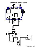
Refrigerant Piping Procedures
When installing/routing the lines set, cap both ends of each tube to prevent material or debris from entering the
tubing.
Prior to connecting the piping, loosely connect the refrigerant gauges to the service ports of the suction and liquid
line service valves. Purge the charging hoses with dry Nitrogen and tighten the hose connections. Remove the service
valve caps and turn the valve stem clockwise (half of a complete turn) in order to unseat the valve and open the
service port. The valve comes in a back seated position from the factory. Keep the piping port sealed until ready to
connect to the vacuum pump.
Cleanliness is of the utmost importance. All horizontal suction piping should be pitched toward the condensing unit
1/2” for every 10’ of pipe. During any brazing procedure, dry Nitrogen should be purged through the fitting at a slow
rate to prevent formation of highly abrasive Copper Oxide. Make sure there are no obstructions to the flow which
would cause pressure build up and the brazed fittings to leak. After leak testing and confirming there are no leaks,
insulate suction line with 1/2” wall thickness Armaflex or equal insulation. Seal all seems using Armaflex 520 Foam
Insulation Adhesive or equivalent. Wrap each seam using line set tape.
Liquid Line Piping Procedure
It is required to use a 1/4” OD Copper tube liquid line. When making connections keep the ends sealed until ready to
fit the tube. First connect the supplied refrigerant drier close to the liquid service valve (king valve) on the receiver.
Downstream, connect the moisture indicating sight glass in an easily visible location. Run the tubing to the Evaporator
Unit (Fan Coil Unit) location and fit to the liquid line stub from the Evaporator Unit (Fan Coil Unit). Energize the
Evaporator Unit (Fan Coil Unit) and set the temperature controller to call for cooling, this will activate the liquid line
solenoid valve. Uncap the suction pipe to prevent obstructed Nitrogen flow. Open the Nitrogen to allow a slow flow
and braze the liquid line fitting. Shut off the Nitrogen and power until suction line is brazed.
Suction Piping Procedure
Slide Aramaflex insulation over the tubing for the entire length of the tube and keep the end of tube sealed during
this procedure. Keep the tubing sealed while running the connection points and fit the suction tube to the Evaporator
Unit (Fan Coil Unit) outlet connection. Install a Schrader Type Access valve at the outlet of the Evaporator Unit (Fan
Coil Unit) to allow for superheat checking. If there are brazed fittings along the length of the tube, apply the insulation
after leak testing.
After all piping ran and ready for the brazing process: Energize the Evaporator Unit (Fan Coil Unit) and set the
temperature controller to call for cooling. Open the liquid line service valve and bleed the nitrogen through both
the liquid and suction line. Loosen the suction gauge hose to relieve pressure during the brazing process. Braze the
connections and cool them off quickly. With the solenoid valve still energized, connect the refrigerant cylinder and
add a small amount of 134a to both the high and low sides.
Testing the Low Ambient Control and Leak Testing
Verify the Johnson control is set at 170 for the cut in and 70 for the differential. Remove one wire from the Johnson
Pressure Control and connect an ohmmeter to its two terminals. With pressure below 100 psi, the meter should read
“open circuit”. Using dry nitrogen slowly increase pressure to 170 psi at which pressure the controller should make and
the meter will read “continuity”.
Continue pressure build up to 200 psi. Check to see if there is a noticeable pressure drop, if so locate and fix leak. With
pressure at 200 psi, check for leaks with a refrigerant leak detector and/or soap bubbles. Confirm pressure holds at 200
psi for 30 minutes. If not check again for leaks and repair, perform another leak test. When it is confirmed there are no
leaks, release the nitrogen pressure and leave the solenoid valve energized.
INSTALLING THE CONDENSING UNIT


