background image

6

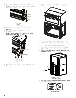
2. 

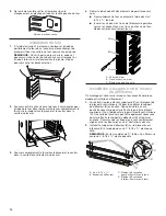
Install a foot on the left rear spacer using a #8-18 x 

3

/

8

screw.  

NOTE:

 Position the foot so the long side of the foot is facing 

toward the top of the oven.

3. 

In the same manner, install a foot on the right rear of 

the oven.

4. 

Install a front foot on the left front spacer using a 

#8-18 x 

3

/

8

" screw.

NOTE:

 Position the foot so the long side of the foot is 

facing toward the inside of the oven.

5. 

In the same manner, install a front foot on the right front of 

the oven.

6. 

Using 2 or more people, place the oven in its upright 

position.

7. 

Go to the “Make Electrical Connection” section in the 

Installation Instructions provided with your built-in oven.

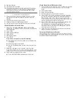
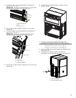
Replace Plastic Spacers

1. 

Remove the screw attaching the plastic spacer (A) to the 

right side of the oven.

2. 

Using the screw removed, install a new plastic spacer (B) 

provided with this kit.

3. 

In the same manner, remove and replace the plastic spacer 

on the left side of the oven.

A

B

C

A. Spacer
B. Foot
C.  #8-18 x 

3

/

8

" screw

A

B

C

A.  Front foot
B.  #8-18 x 

3

/

8

" screw

C. Spacer

A.  Plastic spacer
B.  New plastic spacer

A

B

New plastic spacer

Содержание WOC54EC0HB

Страница 1: ...nless WOC75EC0HV W11123006 30 76 2 cm bronze WOCA7EC0HN W11115049A BUILT IN OVEN SAFETY 2 INSTALLATION REQUIREMENTS 2 Tools and Parts 2 Location Requirements 2 INSTALLATION INSTRUCTIONS 4 Prepare Built In Microwave Oven Combination 4 Remove Oven Door 4 Replace Oven Door 5 Positioning Oven Feet 5 Replace Plastic Spacers 6 Install Oven 7 Install Deflector Kit Bracket 7 Complete Installation 8 SÉCURI...

Страница 2: ...ort surface must be solid level and flush with bottom of cabinet cutout The floor must be able to support a total weight microwave and built in oven of 208 lbs 95 kg for 27 68 6 cm models or 249 lbs 113 kg for 30 76 2 cm models IMPORTANT To avoid damage to your cabinets check with your builder or cabinet supplier to make sure that the materials used will not discolor delaminate or sustain other da...

Страница 3: ...side cleat G 1 2 x 2 13 mm x 51 mm spacer the entire depth of the cutout H Recommended junction box location I 45 8 191 4 11 7 cm 48 9 cm bottom of cutout to floor J 25 63 5 cm minimum depth of cutout 27 68 6 cm Models A 5 8 16 mm top cleat B 271 4 69 2 cm minimum width of flush inset cutout C 257 8 65 7 cm minimum width of opening D 431 8 109 5 cm minimum height of flush inset cutout E 421 2 107 ...

Страница 4: ...nds to remove oven door s 1 Prior to removing the oven door prepare a surface where you will place it This surface should be flat and covered with a soft blanket or use the corner posts from your packaging material 2 Open the oven door 3 Locate the oven door hinge locks in both corners of the oven door and rotate the hinge locks toward the oven door to the unlocked position If the door hinge lock ...

Страница 5: ...the oven cavity to the locked position See Step 3 illustration A in the Remove Oven Door s section for proper locked position 6 Close the oven door 7 When the hinges are properly installed and the door closed there should be an even gap between the door and the control panel If one side of the oven door is hanging lower than the other the hinge on that side is not properly installed Repeat the ste...

Страница 6: ...t on the right front of the oven 6 Using 2 or more people place the oven in its upright position 7 Go to the Make Electrical Connection section in the Installation Instructions provided with your built in oven Replace Plastic Spacers 1 Remove the screw attaching the plastic spacer A to the right side of the oven 2 Using the screw removed install a new plastic spacer B provided with this kit 3 In t...

Страница 7: ...e the deflector bracket B between them Some force may be required to flex the upper vent trim C away from the lower vent trim D Some force may also be required to flex the deflector bracket B and slide it into position Make sure screw holes are properly aligned between the two pieces See the following illustration 2 Install the deflector bracket B to the lower vent piece D using two 8 18 x 1 4 scr...

Страница 8: ...r heat If you do not feel heat or if an error message appears in the display turn off the oven and contact a qualified technician 8 Press OVEN on single ovens to cancel Press UPPER LOWER on double ovens to cancel Check Operation of Microwave Oven 1 Fill a microwave safe container with 1 cup 250 mL of water and place container inside microwave oven Close door firmly 2 Press MICROWAVE 3 Select Cooki...

Страница 9: ... du four doit être robuste horizontale et en affleurement avec le bas de l ouverture découpée dans le placard Le plancher doit être capable de supporter un poids total four à micro ondes et four encastré de 208 lb 95 kg pour les modèles de 27 68 6 cm ou 249 lb 113 kg pour les modèles de 30 76 2 cm IMPORTANT Afin d éviter d endommager les placards consulter l installateur ou le fabricant des placar...

Страница 10: ...ture 1 2 x 2 13 mm x 51 mm H Emplacement recommandé pour le boîtier de connexion I 45 8 191 4 11 7 cm 48 9 cm du fond de l encastrement au plancher J Profondeur minimale de l ouverture 25 63 5 cm Modèles de 27 68 6 cm A Tasseau supérieur de 5 8 16 mm B Largeur minimale de l ouverture intégrée en affleurement 271 4 69 2 cm C Largeur minimale de l ouverture 257 8 65 7 cm D Hauteur minimale de l ouve...

Страница 11: ...Ouvrir la porte du four 3 Identifier les loquets de charnière de la porte du four dans les deux angles de la porte faire pivoter les loquets de charnière vers la porte du four jusqu à la position de déverrouillage Si le loquet de charnière de porte n est pas complètement tourné voir illustration B la porte ne se retirera pas correctement 4 Fermer partiellement la porte pour engager les loquets de ...

Страница 12: ...dans la section Dépose de la des porte s du four pour une position de verrouillage correcte 6 Fermer la porte du four 7 Une fois les charnières correctement installées et la porte fermée il doit y avoir un espace égal entre la porte et le tableau de commande Si l un des côtés de la porte du four est plus bas que l autre la charnière de ce côté ci n est pas correctement installée Répéter les étapes...

Страница 13: ...5 De la même manière installer un pied avant sur le coin avant droit du four 6 À l aide d au moins deux personnes placer le four en position verticale 7 Passer à la section Raccordement électrique des instructions d installation fournies avec le four encastré Remplacement des cales d espacement en plastique 1 Retirer la vis fixant la cale d espacement en plastique A au côté droit du four 2 À l aid...

Страница 14: ...c les trous du châssis du four Nepas serrer excessivement les vis Installation du support de la trousse du déflecteur Ce montage est nécessaire lorsqu un four encastré simple ou double est installé en affleurement 1 Faire fléchir la pièce d évent supérieure C en l éloignant de la pièce d évent inférieure D pour faire glisser le support du déflecteur B entre elles Une certaine force sera peut être ...

Страница 15: ... de courant est correctement alimentée Voir la section Dépannage dans le Guide d utilisation et d entretien 7 Après que le four a fonctionné pendant 5 minutes vérifier qu il y a émission de chaleur Si aucune chaleur n est ressentie ou si un message d erreur apparaît sur l affichage éteindre le four et contacter un technicien qualifié 8 Pour les fours simples appuyer sur OVEN four Pour les fours do...

Страница 16: ...W11115049A 2017 Used under license in Canada All rights reserved Utilisé sous licence au Canada Tous droits réservés 09 17 ...

Отзывы: