background image

2

BUILT-IN MICROWAVE OVEN SAFETY

INSTALLATION INSTRUCTIONS

Tools Recommended

Gather the required tools and parts before starting installation. 
Read and follow the instructions provided with any tools 
listed here.

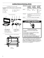
Parts Supplied

Cutout Dimensions

You can be killed or seriously injured if you don't immediately 
 

You


can be killed or seriously injured if you don't follow 

All safety messages will tell you what the potential hazard is, tell you how to reduce the chance of injury, and tell you what can
happen if the instructions are not followed.

Your safety and the safety of others are very important.

We have provided many important safety messages in this manual and on your appliance. Always read and obey all safety 
messages.

This is the safety alert symbol.

This symbol alerts you to potential hazards that can kill or hurt you and others.

All safety messages will follow the safety alert symbol and either the word “DANGER” or “WARNING.”

These words mean:

follow instructions.

instructions.

DANGER

WARNING

Measuring tape

Pencil

Scissors

#2 Phillips screwdriver

⁵⁄₆₄

" drill

A. Trim kit frame
B. Side duct (1)

C. 1" screws (4, plus 2 extra)
D. 1/2" screws (15, plus 2 extra)

E. Anti-tip bracket (1)

F. Bottom duct (1)

G. Bottom bracket (1)
H. Upper duct (1)

I. Template (1)

 A                                  B          C       D             E

F                                    G                   H                I

A. Depth
B. Width

DIM.

OVER 24" 
(61.0 CM) 
BUILT-IN OVEN

OVER 27" 
(68.6 CM) 
BUILT-IN OVEN

OVER 30" 
(76.2 CM) 
BUILT-IN OVEN

Width

22

¹⁄₂

(57.15 cm)

25

¹⁄₂

(64.77 cm)

25

¹⁄₂

(64.77 cm) min.;
28

¹⁄₂

(72.39 cm) max.

Depth

18

¹⁄₂

" (46.99 cm) min. with flush mount receptacle;

19" (48.26 cm) min. without flush mount receptacle

Height

15

³⁄₄

" (40.01 cm) (for all models)

Width

Width

A

15

³⁄₄

"

(40 cm)

3"

(7.6 cm)

B

Содержание MK1150XP, MK1154XP, MK1157XP

Страница 1: ...NSTALLATION INSTRUCTIONS 2 Tools Recommended 2 Parts Supplied 2 Cutout Dimensions 2 Electrical Requirements 3 Microwave Oven Preparation 3 Bottom Duct Assembly 3 Side Duct and Upper Duct Assembly 3 Anti Tip Bracket Installation 4 Microwave Oven Placement 4 Trim Kit Frame Installation 5 SÉCURITÉ DU FOUR À MICRO ONDES ENCASTRÉ 5 INSTRUCTIONS D INSTALLATION 6 Outillage recommandé 6 Pièces fournies 6 ...

Страница 2: ...nd obey all safety messages This is the safety alert symbol This symbol alerts you to potential hazards that can kill or hurt you and others All safety messages will follow the safety alert symbol and either the word DANGER or WARNING These words mean follow instructions instructions DANGER WARNING Measuring tape Pencil Scissors 2 Phillips screwdriver drill A Trim kit frame B Side duct 1 C 1 screw...

Страница 3: ...Electrical Shock Hazard Plug into a grounded 3 prong outlet Failure to follow these instructions can result in death fire or electrical shock Do not use an extension cord Do not use an adapter Do not remove ground prong GROUNDING INSTRUCTIONS For all cord connected appliances The microwave oven must be grounded In the event of an electrical short circuit grounding reduces the risk of electric shoc...

Страница 4: ...acket onto cutout floor using two screws MicrowaveOvenPlacement 1 Slide microwave oven partway into cutout opening NOTE Bottom bracket must be flat against cutout floor in order to correctly engage with anti tip bracket 2 Plug in microwave oven 3 Make sure microwave oven is centered within cutout opening and slide it into place engaging anti tip bracket 4 Drill pilot holes through positioning flan...

Страница 5: ...kit frame A B C D Risque possible de décès ou de blessure grave si vous ne suivez pas immédiatement les instructions Risque possible de décès ou de blessure grave si vous ne suivez pas les instructions Tous les messages de sécurité vous diront quel est le danger potentiel et vous disent comment réduire le risque de blessure et ce qui peut se produire en cas de non respect des instructions Votre sé...

Страница 6: ... Conduit latéral 1 C Vis de 1 4 plus 2 D Vis de 15 plus 2 E Bride antibasculement 1 F Conduit inférieur 1 G Bride du fond 1 H Conduit supérieur 1 I Gabarit 1 A Largeur B Profondeur A B C D E F G H I W i d t h W i d t h A 15 40 cm 3 7 6 cm B DIMENSIONS AU DESSUS DU FOUR ENCASTRÉ 24 61 0 CM AU DESSUS DU FOUR ENCASTRÉ 27 68 6 CM AU DESSUS DU FOUR ENCASTRÉ 30 76 2 CM Largeur 22 57 15 cm 25 64 77 cm 25...

Страница 7: ...er avec la vis existante A Bride du fond B Vis de INSTRUCTIONS DE MISE À LA TERRE Pour tout appareil ménager connecté par un cordon de courant électrique Il faut que le four à micro ondes soit relié à la terre En cas de court circuit électrique la liaison à la terre réduit le risque de choc électrique car le courant électrique dispose d un itinéraire direct d acheminement à la terre Le four à micr...

Страница 8: ...e 1 Placer le cadre de garniture sur le four à micro ondes REMARQUE Le cadre de garniture doit être orienté de telle manière que les lames de claire voie soient inclinées vers l avant vers le bas 2 Veiller à ce que le cadre de garniture soit d aplomb et centré par rapport aux 4 côtés du four à micro ondes Marquer la position du centre des 4 trous de montage du cadre de garniture 3 Enlever le cadre...

Отзывы: