background image

20

8.  

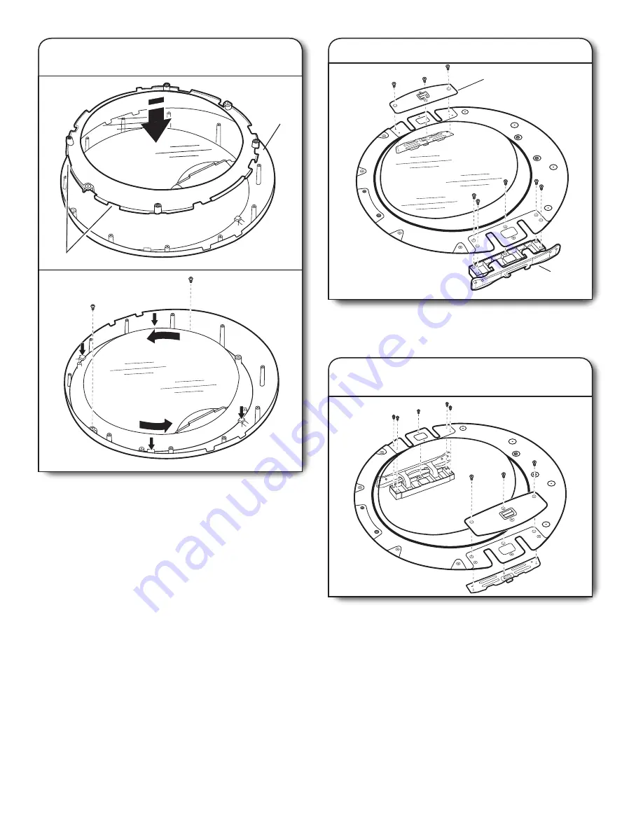
Reinstall hinge and latch on  

opposite sides

Using a TORX T25 screwdriver, reinstall the latch plate, latch 

backing plate, and hinge assembly on the opposite sides from 

which they were removed.

7. 

Remove hinge and latch

Using a TORX

® 

 T25 screwdriver, remove the 3 TORX screws 

securing the latch plate and latch backing plate and the 5 

screws holding the hinge assembly in place.

Hinge

Latch

6.  

Rotate and reassemble outer window 

assembly to trim ring

With the edge with 2 notches at the top, align the notches on 

the outer window assembly with the tabs on the trim ring and 

lower into place as shown in figure A. 

Rotate the outer window assembly counterclockwise to lock 

tabs into place (figure B). Using a Phillips screwdriver, secure 

with 2 screws removed earlier.

IMPORTANT

: Do not overtighten.

Fig. A

Fig. B

Bottom 

of door

Notches

Содержание MED3000BW

Страница 1: ...ystem 14 CONNECT INLET HOSE STEAM MODEL ONLY 15 CONNECT VENT 16 LEVEL DRYER 17 COMPLETE INSTALLATION CHECKLIST 17 DOOR REVERSAL OPTIONAL 18 ELECTRIC DRYER INSTALLATION INSTRUCTIONS INSTALLATION NOTES Date of purchase __________________________________ Date of installation ________________________________ Installer _________________________________________ Model number _____________________________...

Страница 2: ...2 DRYER SAFETY IMPORTANT When discarding or storing your old clothes dryer remove the door ...

Страница 3: ...r installation Check local codes Check existing electrical supply and venting Read Electrical Requirements and Venting Requirements before purchasing parts If using a power supply cord Use a UL listed power supply cord kit marked for use with clothes dryers The kit should contain A UL listed 30 amp power supply cord rated 120 240 volt minimum The cord should be type SRD or SRDT and be at least 4 f...

Страница 4: ...rt Number 279810 If not level clothes may not tumble properly and automatic sensor cycles may not operate correctly For garage installation place dryer at least 18 460 mm above floor If using a pedestal you will need 18 460 mm to bottom of dryer The dryer must not be installed or stored in an area where it will be exposed to water and or weather IMPORTANT Do not operate install or store dryer wher...

Страница 5: ...utral conductor white wire within the dryer If the dryer is installed with a 4 wire electrical supply connection the neutral ground conductor must be removed from the external ground connector green screw and secured under the neutral terminal center or white wire of the terminal block When the neutral ground conductor is secured under the neutral terminal center or white wire of the terminal bloc...

Страница 6: ...e Flexible armored cable or nonmetallic sheathed copper cable with ground wire covered with flexible metallic conduit All current carrying wires must be insulated 10 gauge solid copper wire do not use aluminum at least 5 ft 1 52 m long INSTALL LEVELING LEGS To avoid damaging floor use a large flat piece of cardboard from dryer carton place under entire back edge of dryer Firmly grasp dryer body no...

Страница 7: ...re direct connection Go to Direct Wire Connection 4 wire direct connection Go to Direct Wire Connection Power supply cord 3 wire receptacle NEMA Type 10 30R Go to Power Supply Cord Connection NOTE If local codes do not permit connection of a cabinet ground conductor to neutral wire go to Optional 3 wire connection This connection may be used with either a power supply cord or a direct wire connect...

Страница 8: ...net and be in a horizontal position Do not further tighten strain relief screws at this point Remove the screws from a 3 4 19 mm UL listed strain relief UL marking on strain relief Put the tabs of the two clamp sections C into the hole below the terminal block opening B so that one tab is pointing up A and the other is pointing down D and hold in place Tighten strain relief screws just enough to h...

Страница 9: ...lock cover into slot of dryer rear panel Secure cover with hold down screw Now go to Venting Requirements Connect remaining wires under outer terminal block screws Tighten screws Finally reinsert tab of terminal block cover into slot of dryer rear panel Secure cover with hold down screw Now go to Venting Requirements Connect neutral wire white or center C of power supply cord under center terminal...

Страница 10: ... the removable conduit connector A onto the strain relief threads and tighten securely Put direct wire cable through the strain relief The strain relief should have a tight fit with the dryer cabinet and be in a horizontal position Tighten strain relief screw against the direct wire cable Direct wire cable must have 5 ft 1 52 m of extra length so dryer may be moved if needed Strip 5 127 mm of oute...

Страница 11: ...n screw Place hooked ends of remaining direct wire cable wires under outer terminal block screws hooks facing right Squeeze hooked ends together and tighten screws Finally reinsert tab of terminal block cover into slot of dryer rear panel Secure cover with hold down screw Now go to Venting Requirements 3 Connect neutral wire C B Place hooked end of neutral wire white or center C of direct wire cab...

Страница 12: ...Connect neutral ground wire and neutral wire C E B 1 Prepare to connect neutral ground wire and neutral wire E B A 3 Connect remaining wires 4 Connect external ground wire G A Install the correct strain relief for your electrical connection method as shown on page 8 or 10 Remove center terminal block screw B Remove neutral ground wire E from green external ground conductor screw A Venting Requirem...

Страница 13: ... Must be fully extended and supported in final dryer location Remove excess to avoid sagging and kinking that may result in reduced airflow and poor performance Do not install in enclosed walls ceilings or floors The total length should not exceed 73 4 ft 2 4 m The length of flexible metal vent used must be included in the overall vent system design as shown in the Vent System Chart NOTE If using ...

Страница 14: ...urns as possible Determine vent length and elbows needed for best drying performance Use the following Vent System Chart to determine type of vent material and hood combinations acceptable to use NOTE Do not use vent runs longer than those specified in Vent System Chart Exhaust systems longer than those specified will Shorten life of dryer Reduce performance resulting in longer drying times and in...

Страница 15: ... and replace with new rubber washer 3 Tighten couplings Using pliers tighten the couplings with additional two thirds turn NOTE Do not overtighten Damage to the coupling can result 4 Attach long hose to Y connector and tighten couplings Attach one of the 5 ft 1 5 m inlet hose ends to the Y connector Attach washer cold inlet hose to other side of Y connector Screw on coupling by hand until it is se...

Страница 16: ...er faucet Check that the water faucets are turned on CONNECT VENT 1 Connect vent to exhaust outlet 2 Move dryer to final location Using a 4 102 mm clamp connect vent to exhaust outlet in dryer If connecting to existing vent make sure vent is clean Dryer vent must fit over dryer exhaust outlet and inside exhaust hood Check that vent is secured to exhaust hood with a 4 102 mm clamp Move dryer to fin...

Страница 17: ...er drum interior thoroughly with a damp cloth to remove any dust q Read Dryer Use in your Use and Care Guide q For power supply cord installation plug into a grounded outlet For direct wire installation turn on Power q If you live in a hard water area use of a water softener is recommended to control the buildup of scale through the water system in the dryer Over time the buildup of lime scale may...

Страница 18: ...r door and set aside IMPORTANT If the protective film has not yet been removed from the dryer peel the film from the dryer door before proceeding Using a TORX T25 screwdriver remove the 4 screws securing the door hinge to the dryer and lift up and out to remove the door Place the door on a soft towel or other non scratch surface Reinstall the 4 screws in the holes Reverse door swing round shaped d...

Страница 19: ...he 4 tabs on the trim ring indicated with arrows in the figure A above Then lift out the outer window and retainer up and off the trim ring and set aside B Fig A Fig B 5 Reverse outer window assembly Using a Phillips screwdriver remove the 4 screws from the outer window retainer and lift off the trim ring off the window A Rotate trim ring 180 and secure with the 4 screws removed earlier B Handle F...

Страница 20: ...backing plate and the 5 screws holding the hinge assembly in place Hinge Latch 6 Rotate and reassemble outer window assembly to trim ring With the edge with 2 notches at the top align the notches on the outer window assembly with the tabs on the trim ring and lower into place as shown in figure A Rotate the outer window assembly counterclockwise to lock tabs into place figure B Using a Phillips sc...

Страница 21: ...or from dryer IMPORTANT If the protective film has not yet been removed from the dryer peel the film from the dryer door before proceeding Using a TORX T25 screwdriver remove the 4 screws securing the door hinge to the dryer and lift up and out to remove the door Place the door on a soft towel or other non scratch surface Reinstall the 4 screws in the holes Reverse door swing round shaped door dou...

Страница 22: ...ch plate and latch backing plate and the 5 screws holding the hinge assembly in place Hinge Latch 5 Reinstall hinge and latch on opposite sides Using a TORX T25 screwdriver reinstall the latch plate and latch backing plate with the 3 TORX screws removed earlier and the hinge assembly with the 5 screws on the opposite sides from which they were removed 6 Reinstall inner door assembly Position the d...

Страница 23: ... dryer door frame as shown 3 Remove inner door from outer door Position the door with the inside of the door facing up Using a Phillips screwdriver remove the 13 screws securing the inner door to the outer door Lift off the inner door and set aside NOTE There is a small release tab on each side of the door If the inner and outer door do not separate easily slide a credit card putty knife or simila...

Страница 24: ...ll hinge and latch on opposite sides Using a TORX T25 screwdriver reinstall the latch plate and hinge assembly on the opposite sides from which they were removed Latch Latch 4 Remove hinge and latch from inner door Using a TORX T25 screwdriver remove the 3 Torx screws securing the latch plate and the 5 screws holding the hinge assembly in place Hinge Latch W10558997A W10558999A SP 2012 Whirlpool C...

Отзывы: