Whirlpool KSGG700ESS2 Скачать руководство пользователя страница 13

13

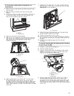
Verify Anti-Tip Bracket Is Installed  

and Engaged

On Ranges Equipped with a Premium Storage Drawer:

1. 

Slide range into final location, making sure rear leveling leg 
slides into anti-tip bracket.

2. 

Remove the premium storage drawer. See the “Remove/ 
Replace Drawer” section.

3. 

Use a flashlight to look underneath the bottom of the range.

4. 

Visually check that the rear range foot is inserted into the slot 
of the anti-tip bracket.

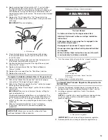
On Ranges Equipped with a Warming Drawer or Baking 
Drawer:

1. 

Slide range into final location, making sure rear leveling leg 
slides into anti-tip bracket. Leave a 1" (2.5 cm) gap between 
the back of the range and the back wall.
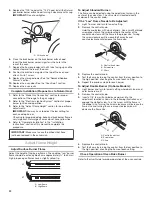
2. 

Place the outside of your foot against the bottom front of the 
warming drawer or baking drawer to keep the range from 
moving, and then grasp the back of the range, as shown.

3. 

Slowly attempt to tilt the range forward.

If you encounter immediate resistance, the range foot is 
engaged in the anti-tip bracket. Go to Step 8.

4. 

If the rear of the range lifts more than 1/2" (1.3 cm) off the 
floor without resistance, stop tilting the range and lower it 
gently back to the floor. The range foot is not engaged in the 
anti-tip bracket.

IMPORTANT:

 If there is a snapping or popping sound when 

lifting the range, the range may not be fully engaged in the 
bracket. Check to see if there are obstructions keeping 
the range from sliding to the wall or keeping the range foot 
from sliding into the bracket. Verify that the bracket is held 
securely in place by the mounting screws.

5. 

Slide the range forward, and verify that the anti-tip bracket is 
securely attached to the floor or wall.

6. 

Slide range back so the rear range foot is inserted into the 
slot of the anti-tip bracket.

7. 

Repeat steps 1 and 2 to ensure that the range foot is 
engaged in the anti-tip bracket.

If the rear of the range lifts more than 1/2" (1.3 cm) off the 
floor without resistance, the anti-tip bracket may not be 
installed correctly. Do not operate the range without anti-
tip bracket installed and engaged. Please reference the 
“Warranty” section of the User Guide to contact service.

8. 

Move the range into its final location. Check that the range 
is level by placing a level on the oven bottom. See the “Level 
Range” section. 

IMPORTANT:

 If the range is moved to adjust the leveling 

legs, verify that the anti-tip bracket is engaged by repeating 
steps 1 to 8.

Electronic Ignition System

Initial Lighting and Gas Flame Adjustments

Cooktop and oven burners use electronic igniters in place of 
standing pilots. When the cooktop control knob is turned to the 
“ignite” position, the system creates a spark to light the burner. 
All cooktop burners will spark, but only the burner with the 
control knob turned to the “ignite” position will produce a flame. 
This sparking continues as long as the control knob is turned to 
the “ignite” position.

When the oven control is turned to the desired setting, sparking 
occurs and ignites the gas.

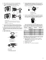
Check Operation of Cooktop Burners

Standard Surface Burners

Push in and turn each control knob to the “ignite” position.

The flame should light within 4 seconds. The first time a burner 
is lit, it may take longer than 4 seconds to light because of air in 
the gas line.

If Burners Do Not Light Properly:


Turn cooktop control knob to the "off" position.


Check that the range is plugged into a grounded 3 prong 
outlet. Check that the circuit breaker has not tripped or the 
household fuse has not blown.


Check that the gas shut-off valves are set to the open position.


Check that burner caps are properly positioned on burner 
bases.

Repeat start-up. If a burner does not light at this point, turn the 
control knobs to the "off" position and contact your dealer or 
authorized service company for assistance. Please reference the 
“Warranty” section of the User Guide to contact service.

If the cooktop "low" burner flame needs to be adjusted for any 
of the burners, see the “Adjust Flame Height” section.

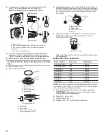
Check Operation of Oven Bake Burner

1. 

Press BAKE.

2. 

Press the Start pad.

The oven burner should light within 8 seconds. The first time 
a burner is lit, it may take longer than 8 seconds to light 
because of air in the gas line.

3. 

After 2 minutes, open the oven door and check that the oven 
is warm.

If Burner Does Not Light Properly:


Press the Off pad.


Check that the range is plugged into a grounded 3 prong 
outlet. Check that the circuit breaker has not tripped or the 
household fuse has not blown.


Check that the gas shut-off valves are set to the open 
position.

Содержание KSGG700ESS2

Страница 1: ... Tip Bracket Is Installed and Engaged 13 Electronic Ignition System 13 Remove Replace Drawer 14 Oven Door 14 Complete Installation 15 GAS CONVERSIONS 16 Propane Gas Conversion 16 Natural Gas Conversion 19 Adjust Flame Height 22 SÉCURITÉ DE LA CUISINIÈRE 24 EXIGENCES D INSTALLATION 26 Outils et pièces 26 Exigences d emplacement 26 Spécifications électriques 29 Spécifications de l alimentation en ga...

Страница 2: ...proved by UL or CSA For more information contact your gas supplier If a gas leak is detected follow the What to do if you smell gas instructions WARNING If the information in these instructions is not followed exactly a fire or explosion may result causing property damage personal injury or death Do not store or use gasoline or other flammable vapors and liquids in the vicinity of this or any othe...

Страница 3: ...lled Install anti tip bracket to floor or wall per installation instructions Slide range back so rear range foot is engaged in the slot of the anti tip bracket Re engage anti tip bracket if range is moved Do not operate range without anti tip bracket installed and engaged Failure to follow these instructions can result in death or serious burns to children and adults Anti Tip Bracket To verify the...

Страница 4: ...serial rating plate The model serial rating plate is located behind the oven door on the top right hand side of the oven frame The range should be located for convenient use in the kitchen Recessed installations must provide complete enclosure of the sides and rear of the range All openings in the wall or floor where range is to be installed must be sealed Cabinet opening dimensions that are shown...

Страница 5: ...g the range is adequate as long as it conforms to the standards listed above Product Dimensions This manual covers several models Your model may appear different from the models depicted Dimensions given are maximum dimensions across all models Model KSGB900 IMPORTANT Range must be level after installation Follow the instructions in the Level Range section Using the cooktop as a reference for leve...

Страница 6: ...d covered with not less than No 28 MSG sheet steel 0 015 0 4 mm stainless steel 0 024 0 6 mm aluminum or 0 020 0 5 mm copper 30 76 2 cm minimum clearance between the top of the cooking platform and the bottom of an uncovered wood or metal cabinet Slide in Cutout B F G A N J L H I M K C E D A 18 45 7 cm upper side cabinet to countertop B 13 33 cm max upper cabinet depth C 30 76 2 cm min opening wid...

Страница 7: ... is grounded Electrical Shock Hazard Plug into a grounded 3 prong outlet Do not remove ground prong Do not use an adapter Do not use an extension cord Failure to follow these instructions can result in death fire or electrical shock WARNING Gas Supply Requirements Observe all governing codes and ordinances IMPORTANT This installation must conform with all local codes and ordinances In the absence ...

Страница 8: ...14 35 5 cm WCP Propane Gas Minimum pressure 11 28 cm WCP Maximum pressure 14 35 5 cm WCP Contact local gas supplier if you are not sure about the inlet pressure Burner Input Requirements Input ratings shown on the model serial rating plate are for elevations up to 2 000 ft 609 6 m For elevations above 2 000 ft 609 6 m ratings are reduced at a rate of 4 for each 1 000 ft 304 8 m above sea level not...

Страница 9: ...e people to move and install range Failure to do so can result in back or other injury Install Anti Tip Bracket 1 Remove the anti tip bracket from the inside of the oven 2 Determine which mounting method to use floor or wall If you have a stone or masonry floor you can use the wall mounting method If you are installing the range in a mobile home you must secure the range to the floor This anti tip...

Страница 10: ...unter to the floor 3 Measure the distance from the top of the cooktop to the bottom of the leveling legs This distance should be the same If it is not adjust the leveling legs to the correct height The leveling legs can be loosened to add up to a maximum of 1 2 5 cm A minimum of 3 16 5 mm is needed to engage the anti tip bracket NOTE If height adjustment is made when range is standing tilt the ran...

Страница 11: ...two figures below depending on the size of the level Check with the level side to side and front to back 2 If range is not level use a wrench or pliers to adjust leveling legs up or down until the range is level NOTE Range must be level for satisfactory baking performance and best cleaning results using AquaLift Self Clean Technology 3 Use a 15 16 2 4 cm combination wrench and an adjustable wrench...

Страница 12: ...o not put the wrong size burner cap on the burner base 7 Plug into a grounded 3 prong outlet A B A Incorrect B Correct Electrical Shock Hazard Plug into a grounded 3 prong outlet Do not remove ground prong Do not use an adapter Do not use an extension cord Failure to follow these instructions can result in death fire or electrical shock WARNING AUX Small cap Auxiliary Medium cap Semi Rapid Large c...

Страница 13: ...Check that the range is level by placing a level on the oven bottom See the Level Range section IMPORTANT If the range is moved to adjust the leveling legs verify that the anti tip bracket is engaged by repeating steps 1 to 8 Electronic Ignition System Initial Lighting and Gas Flame Adjustments Cooktop and oven burners use electronic igniters in place of standing pilots When the cooktop control kn...

Страница 14: ...s Check Operation of Oven Broil Burner 1 Close the oven door 2 Press BROIL 3 Press the Start pad The oven burner should light within 8 seconds The first time a burner is lit it may take longer than 8 seconds to light because of air in the gas line 4 After 2 minutes open the oven door and check that the oven is warm If Burner Does Not Light Properly Press the Off pad Check that the range is plugged...

Страница 15: ...o remove waxy residue caused by shipping material Dry thoroughly with a soft cloth For more information see the Range Care section of the User Guide 7 Read the User Guide 8 Turn on surface burners and oven See the User Guide for specific instructions on range operation NOTE Odors and smoke are normal when the oven is used the first few times If Range Does Not Operate Check the Following Household ...

Страница 16: ...ulator Natural Gas to Propane Gas 1 Remove the premium storage drawer warming drawer or baking drawer See the Remove Replace Drawer section 2 Locate gas pressure regulator at rear of the drawer compartment IMPORTANT Do not remove the gas pressure regulator WARNING Tip Over Hazard A child or adult can tip the range and be killed Install anti tip bracket to floor or wall per installation instruction...

Страница 17: ... changing it Press nut driver down onto the gas orifice spud and remove by turning it counterclockwise and lifting out Set gas orifice spud aside 4 Remove the orifice spuds shipped in the literature package in the oven Gas orifice spuds are stamped with a number and have a groove in the hex area Replace the Natural gas orifice spud with the correct propane gas orifice spud Refer to the following c...

Страница 18: ... onto the gas orifice spud and remove by turning the Natural gas bake burner orifice spud counterclockwise to remove The spud will be stamped with a 47 7 Replace the 47 spud with a 56 spud Install the propane gas bake burner orifice spud turning it clockwise until snug IMPORTANT Do not overtighten 8 Position the back of the bake burner over the oven orifice and then align the holes for the screws ...

Страница 19: ...ortant The small inner cone should have a very distinct blue flame 1 4 to 1 2 6 35 mm to 1 3 cm long The outer cone is not as distinct as the inner cone propane gas flames have a slightly yellow tip 4 Refer to Complete Installation in the Installation Instructions section of this manual to complete this procedure x x x A A Orifice hood IMPORTANT Make sure to save the orifices that have just been r...

Страница 20: ...s orifice spud in the nut driver while changing it Press nut driver down onto the gas orifice spud and remove by turning it counterclockwise and lifting out Set gas orifice spud aside 4 Gas orifice spuds are stamped with a number on the side Replace the propane gas orifice spud with the correct Natural gas orifice spud Refer to the following chart for the correct Natural gas orifice spud placement...

Страница 21: ...lace the 56 spud with a 47 spud Install the Natural gas bake burner orifice spud turning it clockwise until snug IMPORTANT Do not overtighten 8 Position the back of the bake burner over the oven orifice and then align the holes for the screws 9 Reattach the bake burner with 2 screws 10 Position the front of the oven bottom panel toward the front frame and then lower the rear of the oven bottom pan...

Страница 22: ...ORTANT Make sure to save the orifices that have just been replaced in the conversion A Low flame B High flame A B To Adjust Standard Burner The flame can be adjusted using the adjustment screw in the center of the valve stem The valve stem is located directly underneath the control knob If the Low Flame Needs to Be Adjusted 1 Light 1 burner and turn to lowest setting 2 Remove the control knob Hold...

Страница 23: ... tips blowing or lifting of flame should occur A A Gas pressure regulator A B A Screws B Oven bottom 4 If the oven bake flame needs to be adjusted locate the air shutter near the center rear of the drawer cavity behind the access panel Loosen the locking screw and rotate the air shutter until the proper flame appears Tighten locking screw 5 Push the Off pad when finished 6 Reinstall the oven botto...

Страница 24: ...W11398805A 2019 All rights reserved Used under license in Canada Tous droits réservés Utilisé sous licence au Canada 11 19 ...

Отзывы: