


WHIRLPOOL CONSUMER SERVICES
Models AVM595 WH
AVM595 BL
Page 13 of 14
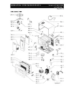
PARTS LIST
Item
Part No
Description
AVM595 WH
AVM595 BL
001 0 4819 442 39108 4819 902 39723 Cabinet
001 1 4819 404 79411 4819 404 79411 Bracket
001 2 4819 902 00714 4819 902 00714 Holder
011 0 4819 462 88055 4819 462 88055 Foot
040 0 4819 417 19596 4819 417 19596 Hinge, upper
040 1 4819 417 19597 4819 417 19597 Hinge, lower
121 0 4819 442 39112 4819 442 39112 Door, inner
121 1 4819 459 48867 4819 459 48867 Door frame
130 0 4819 404 79412 4819 404 79412 Door lock
130 1 4819 492 68825 4819 492 68825 Spring
130 2 4819 528 38457 4819 528 38457 Cam
133 0 4819 535 38157 4819 535 38157 Lock
141 0 4819 902 00718 4819 902 00726 Oven glass outer
142 0 4819 442 39113 4819 442 39113 Inner glass PE
143 0 4819 459 48866 4819 902 00725 Door frame outer
246 0 4819 418 79728 4819 418 79728 Turntable glass
264 0 4819 535 78142 4819 535 78142 Crosspiece
305 0 4819 902 00719 4819 902 00727 Switch
320 0 4819 902 00721 4819 902 00728 Cover
321 0 4819 902 00644 4819 902 00644 Display glass
404 0 4819 131 58019 4819 131 58019 Magnetron
404 1 4819 462 38901 4819 462 38901 Cover
404 2 4819 404 79413 4819 404 79413 Holder
406 0 4819 361 18292 4819 361 18292 Motor for rotary plate
412 0 4819 902 00716 4819 902 00716 Transformer, HT
420 0 4819 902 00583 4819 902 00583 Capacitor HT 0.95
µ
F
421 0 4819 902 00535 4819 902 00535 Filter, mains
421 1 4819 902 00717 4819 902 00717 Cable
426 0 4819 130 38078 4819 130 38078 Diode HV MW
441 0 4819 361 18452 4819 361 18452 Fan motor
441 1 4819 404 79414 4819 404 79414 Holder
443 0 4819 515 28197 4819 515 28197 Fan
490 0 4819 902 00715 4819 902 00715 Cable, mains
500 0 4819 902 00722 4819 902 00722 Control unit
561 0 4819 282 48274 4819 282 48274 Thermostat 125°C
562 0 4819 282 48248 4819 282 48248 Thermostat 165°C
562 1 4819 902 00713 4819 902 00713 Holder
632 0 4819 902 00577 4819 902 00577 Switch
633 0 4819 902 00611 4819 902 00611 Switch
651 0 4819 134 28051 4819 134 28051 Lamp
743 0 4819 462 38899 4819 462 38899 Fan motor cover
770 0 4819 462 38898 4819 462 38898 Air guide
770 1 4819 462 38897 4819 462 38897 Air guide
770 2 4819 462 38896 4819 462 38896 Air guide
774 0 4819 442 39109 4819 442 39109 Cover upper wave guide
774 1 4819 442 39111 4819 442 39111 Cover lower wave guide
794 0 4819 532 68844 4819 532 68844 Spacer


