


WHIRLPOOL CONSUMER SERVICES
Models 6AKM157/IX/2
6AKM157/IX/3
6AKM157/WH/2
6AKM157/WH/3
Page 9 of 9
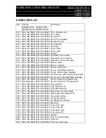
SPARE PARTS LIST
Item
Part No
Description
6AKM157/IX/2
AKM157/IX/3
6AKM157/WH/2 AKM157/WH/3
031 0 4812 442 69097 4812 442 69097 Hob, stainless steel
031 0 4812 442 69098 4812 442 69098 Hob, white
031 1 4812 442 69096 4812 442 69096 Hob bottom
033 0 4812 458 58206 4812 458 58206 Grid for hob adaptor
084 0 4819 905 00768 4819 905 00768 Damper for grid
241 0 4812 458 58135 4812 458 58135 Grid left/right
241 1 4812 458 58134 4812 458 58134 Grid right
331 0 4812 412 58851 4812 412 58851 Knob, black
331 0 4812 412 58852 4812 412 58852 Knob, white
331 1 4812 532 38007 4812 532 38007 Gasket
470 0 4812 360 68286 4812 360 68286 Spreader, burner small
470 1 4812 360 68287 4812 360 68287 Spreader, burner medium
470 3 4812 360 68285 4812 360 68285 Spreader, burner, ultra rapid
471 0 4812 360 78083 4812 360 78078 Burner, small
471 1 4812 360 78084 4812 360 78079 Burner, medium
471 3 4812 360 68092 4812 360 78077 Burner, ultra rapid
473 0 4812 360 78081 4812 360 78081 Cover, small flame spreader
473 1 4812 360 68288 4812 360 68288 Cover, medium flame spreader
473 3 4812 360 68094 4812 360 68094 Centre cover, ultra rapid flame spreader
473 4 4812 360 68095 4812 360 68095 Outer cover, ultra rapid flame spreader
474 0 4812 310 38567 Not applicable
Set of nozzles G20 (Natural gas)
474 0 Not applicable
4812 310 38571 Set of nozzles G31 (Propane gas)
571 0 4812 360 58224 4812 360 58224 Tap small 0.27
571 1 4812 360 58225 4812 360 58225 Tap medium 0.34
571 2 4812 360 58226 4812 360 58226 Tap ultra rapid 0.70
591 0 4812 252 68022 4812 252 68022 Spark plug, small & medium
591 1 4812 252 68007 4812 252 68007 Spark plug, ultra rapid burner
595 0 4819 905 00893 4819 905 00893 Generator, ignition
595 1 4812 140 38001 4812 140 38001 Connection block
703 0 4819 526 48423 4819 526 48423 Coupling piece (Elbow)
703 1 4812 530 48205 4812 530 48205 Manifold
703 2 4812 530 48275 4812 530 48275 Tube front, right
703 3 4812 530 48276 4812 530 48276 Tube front, left
703 4 4812 530 29051 4812 530 29051 Tube back, right
703 5 4812 530 29052 4812 530 29052 Tube back, left
794 0 4819 532 68754 4819 532 68754 Gasket
900 0 4812 404 38569 4812 404 38569 Tap to manifold clamp
900 1 4812 404 38534 4812 404 38534 Fastener
930 0 4812 404 48662 4812 404 48662 Fastener, spark plug


