Page 3
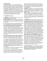
PUSH BUTTONS
4 POSITION
SLIDE SWITCH
GROOVE ON SIDE OF ALUMINUM
CAST COVER USED TO SLIDE IN
THE TWO CARRIAGE BOLTS
(ITEM 11) OF THE MOUNTING
BRACKET
BACKLIGHTED
FUNCTION SWITCHES
11
12
6
13
10
17
1
14
15
16
7 8
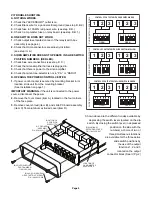
INSTALLATION
RECOMMENDATIONS
1.
Remove mounting bracket
(Item 6) from relay/switch
box assembly (Item 17)
by loosening the two
acorn nuts (Item 10) and
sliding the mounting bracket
off the cast aluminum
cover’s side grooves.
2.
Choose a location for the
PCC-S9R and secure the
mounting bracket firmly
to the mounting surface
with customer supplied
hardware.
NOTE:
The Mounting Bracket
may be installed in any position,
as long as the relay/switch box
assembly can slide in and out from
the mounting bracket, and all switches
are easily accessible.
3.
Wire the unit (See Pg. 2) and slide
the unit into position inside the mounting
bracket. Finally, tighten the two acorn
nuts (Item 10) located on each side
of the PCC-S9R.
QTY
*
1
1
REF
REF
REF
1
REF
REF
REF
REF
REF
REF
REF
1
ITEM
*
1
5
6
7
8
9
10
11
12
13
14
15
16
17
PART NUMBER
01-0881403-00
41-0000000-85C
01-0481403-00
07-241559-000
10-0340730-01
10-0340731-01
01-0415852-01
13-104318-120
14-104069-080
16-1021220-45
16-1031060-04
41-1101040-85C
08-0115440-00C
41-1712060-30C
01-0285545-00
DESCRIPTION
PCC-S9R FINAL ASSEMBLY
PB COVER
INSTALLATION KIT, MODEL PCC-S9R
BRACKET, BAIL STRAP PLASTIC
LABEL, FUNCTION (W/WHITE LETTERS)
LABEL, FUNCTION (W/WHITE LETTERS)
SCREW KIT
10-24 ACORN NUT STEEL ZINC
BOLT, 10-24 1/2“ CARRIAGE
WASHER, 10 INTERNAL TOOTH LOCK
#10 SPLIT LOCKWASHER
SLIDE SWITCH
SLIDE SWITCH KNOB
PUSH BUTTON SWITCHES
PCC-S9R RELAY/SWITCH BOX ASSY
PA
R
T
O
F
ITEM
5
PA
R
T
O
F
ITEM
9


