P84394 F
Sheet 3 of 4
1.
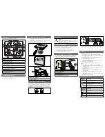
This RSS model can be flush mounted to a standard single-gang backbox (Figure A), 4” or 100mm backbox (Figure B) or double-gang backbox (Figure C). It can
also be surface mounted to a 4” or 100mm backbox (Figure B), double-gang backbox (Figure C) or the SHBB (Figure D). Mounting hardware for each mounting
option is supplied.
2.
Conduit entrances to the backbox should be selected to provide sufficient wiring clearance for the installed product. Do not pass additional wires (used for other
than the signaling appliance) through the backbox. Such additional wires could result in insufficient wiring space for the signaling appliance.
3.
When terminating field wires, do not use more lead length than required. Excess lead length could result in insufficient wiring space for the appliance.
4.
Use care and proper techniques to position the field wires in the backbox so that they use minimum space and produce minimum stress on the product. This is
especially important for stiff, heavy gauge wires and wires with thick insulation or sheathing.
5.
This RSS model has an integrated Strobe Mounting Plate (SMP) which must be oriented correctly when it is mounted to the backbox. Turn the SMP so that the
arrow above the words “Horizontal Strobe” points to the top side.
6.
Move the selector switch to the desired candela setting. The setting is indicated by a pointer and can be seen on the bottom side of the lens. See Figures 3 and 4
below.
7.
Mount the SMP first to the backbox. Next slide the cover over the SMP until the 2 snaps of the cover engage with the SMP.
8.
The cover can be removed from the strobe assembly once engaged. See Figure 5.
Figure 3:
95
CANDELA
POINTER
BOTTOM VIEW
30
15
75
NOTE
: The RSS Multi-Candela come pre-set at 15cd.
Figure 4:
CANDELA
BACK VIEW
SELECTOR
WARNING: THE CANDELA SELECT SWITCH MUST BE FIELD SET TO THE REQUIRED CANDELA INTENSITY BEFORE INSTALLATION.
WHEN CHANGING THE SETTING OF THE CANDELA SELECT SWITCH, MAKE CERTAIN THAT IT “CLICKS” IN PLACE. AFTER CHANGING
THE CANDELA SETTING, THE APPLIANCE MUST BE RETESTED TO VERIFY PROPER OPERATION. IMPROPER SETTING OF THE CANDELA
SELECT SWITCH, MAY RESULT IN OPERATION AT THE WRONG CANDELA, WHICH COULD RESULT IN PROPERTY DAMAGE AND
SERIOUS INJURY OR DEATH TO YOU AND/OR OTHERS.
Figure 5: Cover Removal
1.
Hold flat screwdriver near the tip and insert the tip about
1/8” into one of the slots in the cover as shown.
2.
Pull straight down as shown to pop off cover.
CAUTION:
Prying, turning or pivoting with screwdriver in
order to remove the cover may result in damage to ceiling.
WARNING: REMOVAL OF THE COVER AT THE BACK OF THE MOUNTING PLATE COULD RESULT IN SEVERE ELECTRIC SHOCK.
WARNING: THE RSS STROBE APPLIANCE IS A "FIRE ALARM DEVICE - DO NOT PAINT."
WARNING: WHEN INSTALLING STROBES IN AN OPEN OFFICE OR OTHER AREAS CONTAINING PARTITIONS OR OTHER VIEWING
OBSTRUCTIONS, SPECIAL ATTENTION SHOULD BE GIVEN TO THE LOCATION OF THE STROBES SO THAT THEIR OPERATING EFFECT
CAN BE SEEN BY ALL INTENDED VIEWERS, WITH THE INTENSITY, NUMBER, AND TYPE OF STROBES BEING SUFFICIENT TO MAKE SURE
THAT THE INTENDED VIEWER IS ALERTED BY PROPER ILLUMINATION, REGARDLESS OF THE VIEWER'S ORIENTATION. FAILURE TO
DO SO COULD RESULT IN PROPERTY DAMAGE AND SERIOUS INJURY OR DEATH TO YOU AND/OR OTHERS.
WARNING: A SMALL POSSIBILITY EXISTS THAT THE USE OF MULTIPLE STROBES WITHIN A PERSON'S FIELD OF VIEW, UNDER
CERTAIN CIRCUMSTANCES, MIGHT INDUCE A PHOTO-SENSITIVE RESPONSE IN PERSONS WITH EPILEPSY. STROBE REFLECTIONS IN A
GLASS OR MIRRORED SURFACE MIGHT ALSO INDUCE SUCH A RESPONSE. TO MINIMIZE THIS POSSIBLE HAZARD, WHEELOCK
STRONGLY RECOMMENDS THAT THE STROBES INSTALLED SHOULD NOT PRESENT A COMPOSITE FLASH RATE IN THE FIELD OF VIEW
WHICH EXCEEDS FIVE (5) Hz AT THE OPERATING VOLTAGE OF THE STROBES. WHEELOCK ALSO STRONGLY RECOMMENDS THAT THE
INTENSITY AND COMPOSITE FLASH RATE OF INSTALLED STROBES COMPLY WITH LEVELS ESTABLISHED BY APPLICABLE LAWS,
STANDARDS, REGULATIONS, CODES AND GUIDELINES.
NOTE:
NFPA 72/ANSI 117.1 conform to ADAAG Equivalent Facilitation Guidelines in using fewer, higher intensity strobes within the same protected area.
CAUTION:
Check the installation instructions of the manufacturers of other equipment used in the system for any guidelines or restrictions on wiring and/or
locating Notification Appliance Circuits (NAC) and notification appliances. Some system communication circuits and/or audio circuits, for example, may require
special precautions to assure immunity from electrical noise (e.g. audio crosstalk).