


To reduce the risk of electric shock the user should not
remove the cover. All operating and safety instructions
should be followed. The unit should be kept clear of
water, fluids and moisture and not be operated in damp
conditions. The unit should be operated in a well
ventilated environment. The unit should be kept away
from excessive heat sources such as radiators and if
racked with other power amplifiers there should be a
free air flow to vent out the heat produced (check with
dealer). The unit must only be connected to a power
supply as shown on the rear of the unit with the IEC
cable (or similar) provided. The power cord must be
situated or routed so as not to be walked upon or
pinched or objects placed upon it with special attention
to the area where the power cable enters the IEC
socket at the unit. The power cable should be
disconnected during prolonged non usage. The user
should not attempt to service the unit or use the unit in
any way except as described in this manual. For
service and repair your dealer should be contacted.
This unit complies with relevant safety regulations.
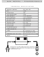
POWER NOTICE FOR SAFETY
All British and European countries use a nominally
230v mains power supply. In practise this varies
between 220v and 240v. In the USA the nominal
supply is 115v and 100v in Japan. This unit is set to
the correct voltage in the factory and this can be
checked from the label on the rear panel. If you
intend to use this crossover in a country which has
a different mains supply voltage, you should
consult your dealer for advice. As there are no user
serviceable components inside the crossover, and
high voltages are present, DO NOT remove the
covers! Be sure to make all audio connections to
the crossover before connecting to the mains
supply.
Safety Instructions
P L E A S E R E A D T H E S E I M P O R TA N T
I N S T R U C T I O N S .
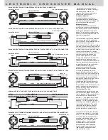
See picture above for key descriptions
1. Power switch
should be pressed in to turn on the
power.
2.
The Power LED
indicates that the unit is ON.
3.
Input Level
rotary c10dB gain is available.
4.
Peak LED
indicates when the input signal is
overloading the equaliser.
5.
Low Cut
switch enables frequencies below 40Hz to
be attenuated.
6.
High Cut
switch enables frequencies above 15kHz
to be attenuated.
7.
Low level
rotary pot controls the level (dB) of the low
frequency as chosen by control 8.
8.
Frequency
rotary pot selects the crossover point
that occurs between the low and high in stereo mode
and the low and mid in mono mode.
9.
x1/x10
switch selects the range of the frequency
rotary pot (no. 8 in the above diagram)
10.
The High/Mid out
rotary pot controls the level (dB)
of the low/mid frequency as chosen by control 8. This
level control is Mid in mono mode and High in stereo
mode.
11.
CD Horn EQ
switch enables a fixed equalisation
curve boost at 10kHz implemented on your
compression driver (CD) horn when the switch is
pressed in.
,
,
12.
Stereo/Mono
switch (mono when in )
13.
Stereo/Mono
switch LED indicator
14.
The High out
rotary pot controls the level (dB) of
the high frequency in mono mode and in stereo mode.
15.
Only in mono mode
This controls the crossover
point between the mid and high units.
16. As no.9 above when in mono mode for high
channel. In stereo mode as no.9 for channel two.
These control no.in the key relate to Mono
operation - in Stereo mode they have same
key descriptions as channel one.
L E C T R O N I C
C R O S S O V E R
M A N U A L
3 4 5 6 7 8 9 10 11 12 13 15 16 14 1 2


