background image

Test signal: Pink Noise, bandwidth limited from 22Hz to 22kHz

1/8 power is typical of program material with occasional clipping. Refer to these figures for most applications.

1/3 power represents program material with extremely heavy clipping.

6

SPECIFICATIONS

4x1000W

0

.7

1

.

5

1

6

0

.

0

1

6

0

.

0

0

.

0

54

6.

0

1

37.6

110V

22

0V

stan

db

y

LO

AD

4

Ω/

CH

1

/8 p

ower

1

/3 p

ower

8Ω/

CH

4

Ω/

CH

8Ω/

CH

Dissipate

d

L

ine C urrent

(

A

)

I

N

OU

T

Power

(W )

Thermal D issipation

k

cal

/

h

B

tu

/

h

4

27.9

3.2

6.3

5

.2

10

.

4

7.

5

15

.

0

2

5

.

1

1

2.6

69

4

.

4

500

.

0

1

9

4

.

4

663.6

1

67.2

114

8.6

8

50

.

0

298.6

101

9.2

2

5

6.8

1

6

4

6.

1

1

333.3

3

1

2.8

10

67.3

269.

0

276

4

.2

2266.7

4

97.6

1

698.

0

This power is measured by using a 20ms pulse of 1KHz sine wave at 1% total harmonic distortion.

8.7Vrms(+21dBu)(Default Gain)

≥90dB

±0.2dB

≥1000

100v~240VAC

50~60Hz

483x44x465mm

9kg

13kg

4

X

1500

W

4

X

1000

W

4

X

1

7

00

W

4

X 2

550

W

2X 2

000

W

2X 3

000

W

2X 3

400

W

2X

5100

W

89.

4V

10

9.

5V

0.05%

0.05%

0.05%

4

X 289

0

W

4

X 3

5

7

0

W

2X

5

78

0

W

2X 7

140

W

≥105dB (Default Gain)

483x44x370mm

20kΩ(Balanced), 10kΩ(Unbalanced)

Power under-voltage protection

Amplifier output DC protection

Thermal Protection

Temperature Power Control

Overload Power Control

Rated Power

(THD=1%

Each channel 

works simultaneously with 

continuous sinusoidal 1KHz)

4Ω/Bridging*

8Ω/Stereo

4Ω/Stereo

2Ω/Stereo*

16Ω/Bridging

8Ω/Bridging

Output RMS voltage (THD=1%,1kHz)

THD+N (10% Rated Power, typical)

Max. Input Level

Gain range (Rated Power

1KHz)

IMD-SMPTE (10% Rated Power, typical)

DIM30 (10% Rated Power, typical)

Crosstalk (20Hz-1kHz,below Rated Power)

Freq response (10% Rated Power,20Hz-20kHz,8Ω)

Input impedance

Damping factor (8Ω, 20Hz-200Hz)

SNR (A weighted 20Hz-20kHz)

Power supply

Protective Function

Size

Height×Width×Depth mm

Net Weight

21dB~39dB

23dB~41dB

Default Gain (Rated Power

1KHz)

25dB

23dB

DP- 4150D

DP- 4100D

Model

110V

22

0V

stan

db

y

LO

AD

4

Ω/

CH

1

/8 p

ower

1

/3 p

ower

8Ω/

CH

4

Ω/

CH

8Ω/

CH

Dissipate

d

L

ine C urrent

(

A

)

I

N

OU

T

ower

(W )

Thermal Dissipation

k

cal

/

h

B

tu

/

h

P

6

41

.9

4

.7

9.

5

7.8

15

.7

11

.2

22.

4

37.7

1

8.8

1041

.7

7

50

.

0

29

1

.7

99

5

.

4

2

50

.8

1

723.

0

1

27

5

.

0

44

8.

0

15

28.8

38

5

.3

2

4

69.

1

2

000

.

0

4

69.

1

1

6

01

.

0

40

3.

5

414

6.3

3

400

.

0

7

4

6.3

2

54

7.

0

4x1500W

0

.7

1

.

5

1

6

0

.

0

1

6

0

.

0

0

.

0

54

6.

0

1

37.6

*1W=0.860kal/h,1BTU=0.252kcal

Содержание DP-D Series

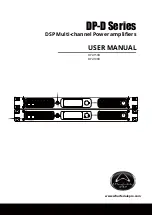
Страница 1: ...DP D Series DSP Multi channel Power amplifiers USER MANUAL www wharfedalepro com DP 4150D DP 4100D ...

Страница 2: ...1 IMPORTANT WARNINGS SAFETY INSTRUCTIONS ...

Страница 3: ...ough the supplied control software This high quality DSP delivers granular editing of EQ Limiting Delay phase and filtering to the signal path allowing a DP D amp to become the system controller as well as the power amplifier This DSP removes the need for additional external signal processing Input connectivity is handled either by discrete analogue XLR connectors on the rear panel or by the RS485 c...

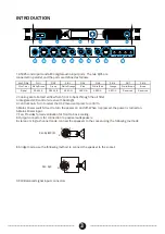
Страница 4: ...witch Used to turn the power on and off When I is pressed the power is turned on 6 Mains Power input 7 Fan Provides forced ventilation for front to back cooling 8 Output connectors for connection to passive loudspeakers In stereo or single channel mode connect the speakers to the socket using the following methods In bridge mode use the following method to connect the speaker to the socket 9 XLR Ba...

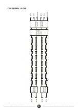
Страница 5: ...ter Mute OutA OutB 0 80dB EQ Filter Delay Limiter Mute 0 80dB EQ Filter Delay Limiter Mute OutC OutD 0 80dB EQ Filter Delay Limiter Mute AES3 4 InC InD Normal Bridge 4X4 Audio Matrix GainB GainA GainC GainD Inverter Invertet Inverter Inverter Normal Bridge S ource Selection ...

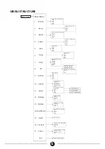
Страница 6: ...CH_B CH_C CH_D EXIT Gain Control CH_A CH_B CH_C CH_D EXIT Audio Source Selections CH_A CH_B CH_C CH_D EXIT Inverter Phase Control C _A CH_B CH_C CH_D EXIT 12 Standby 13 Address 14 Save Recall 16 Contrast Exit Temperature Value Protection Mode Output Voltage Current Standby Setting Normal Standby EXIT Save and Retrieve Setting Save Recall Clear EXIT 485Parameter Setting Address Baudrate EXIT Factor...

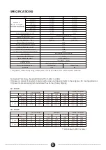
Страница 7: ...ed 10kΩ Unbalanced Power under voltage protection Amplifier output DC protection Thermal Protection Temperature Power Control Overload Power Control Rated Power THD 1 Each channel works simultaneously with continuous sinusoidal 1KHz 4Ω Bridging 8Ω Stereo 4Ω Stereo 2Ω Stereo 16Ω Bridging 8Ω Bridging Output RMS voltage THD 1 1kHz THD N 10 Rated Power typical Max Input Level Gain range Rated Power 1KH...

Страница 8: ...of purchase In the event of malfunction contact your authorised Wharfedale Pro dealer or distributor for information Be aware that warranty details may differ from country to country Contact your dealer or distributor for information These terms do not infringe your statutory rights WHARFEDALE PRO LIMITED WARRANTY February 2020 ...

Отзывы: