Whalen Peruzzi SPLS-PE48D Скачать руководство пользователя страница 43


19


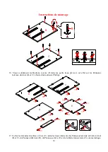
Instructions de montage
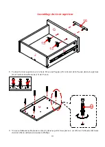
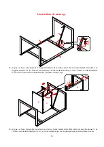
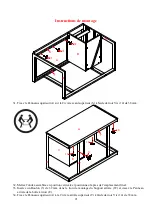
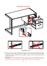
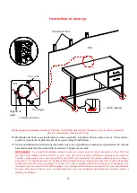
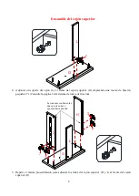


27.


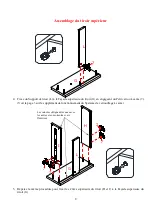
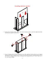
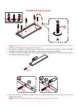
Fixez la Civière avant supérieur (S) au Cadre latéral gauche (Q) et au Panneau latéral gauche de la boîte 

à tiroir (B) à l'aide de quatre Boulons (1) de 15 mm et de quatre Rondelles (5 et 6). 
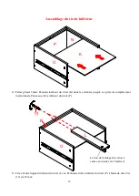
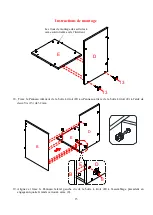
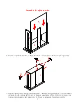


28.


Fixez le Panneau inférieur de la boîte à tiroir (D) au Support métallique de la boîte à tiroir (X) à l'aide de 

trois Vis (12) de 25 mm. 

Q

B

D

R

X

12

12

12

La languette métallique en saillie est orientée vers le 

bas lorsque l'appareil est tourné vers le haut. 


Q

B

S

R

1 5

6

B

S

1 5

6

Содержание Peruzzi SPLS-PE48D

Страница 1: ...g assembly or if parts are missing DO NOT return this item to the store where it was purchased Please call our toll free customer service number and have your instructions and parts list ready to prov...

Страница 2: ...ove all parts from carton and separate into groups as indicated on part list Please ensure all parts are included prior to assembly Use of power tools to complete assembly is not recommended MAXIMUM R...

Страница 3: ...let IF NECESSARY CAM LOCK SYSTEM OPERATION HOW THE KNOCK DOWN KD ASSEMBLY SYSTEM WORKS 1 Screw the Cam Bolt into the threaded inserts on the panel Connect both panels together making sure Cam Bolt goe...

Страница 4: ...THIS PRODUCT IS ONLY A DETERRENT IT IS NOT A SUBSTITUTE FOR PROPER ADULT SUPERVISION USE OF TIP OVER RESTRAINTS MAY ONLY REDUCE BUT NOT ELIMINATE THE RISK OF TIP OVER Children have died from furniture...

Страница 5: ...E Drawer Box Back Panel Qty 1 F Cross Bar Qty 1 G Upper Drawer Front Qty 1 H Upper Drawer Left Side Qty 1 I Upper Drawer Right Side Qty 1 J Upper Drawer Back Panel Qty 1 K Drawer Bottom Panel Qty 2 L...

Страница 6: ...Washer 6 Flat Washer 7 Small Cam Lock Qty 4 1 extra Qty 8 1 extra Qty 8 1 extra Qty 10 1 extra 8 Large Cam Lock 9 Cam Bolt 10 M6x30 mmWood Dowel 11 M8x30mm WoodDowel Qty 16 1 extra Qty 26 1 extra Qty...

Страница 7: ...e all the hardware and required parts Assemble the unit on a carpeted floor or the empty carton to avoid any scratch 2 Securely screw the Cam Bolts 9 into the designated small holes on the Upper Drawe...

Страница 8: ...Drawer Front G by engaging one Small Cam Lock 7 Refer to page 3 on Cam Lock system operation supplement 5 Repeat the same procedure to attach the Upper Drawer Sides H and I to the Upper Drawer Front G...

Страница 9: ...r Drawer Front G 7 Fasten the Upper Drawer Back Panel J to the Upper Drawer Sides H and I and Drawer Bottom Support L with six 32 mm Screws 13 Make sure that Drawer Bottom Panel K fits securely into t...

Страница 10: ...drawer upright Attach one Handle 16 to the front of the Upper Drawer Front G with two 25 mm Bolts 15 9 Securely screw the Cam Bolts 9 into the designated small holes on the Lower Drawer Front M using...

Страница 11: ...rawer Sides N and O Lower Drawer Back Panel P and the other Drawer Support L as shown 11 Fasten the Lower Drawer Back Panel P between the Lower Drawer Side Panels N and O with four 32 mm Screws 13 N P...

Страница 12: ...rawer Bottom Panel K into the grooves until fully inserted into the Lower Drawer Back Panel P 13 Fasten the other Drawer Bottom Support L to the Lower Drawer Back Panel P with two 32 mm Screws 13 N K...

Страница 13: ...Lower Drawer Front M to the Lower Drawer Sides N and O and Drawer Bottom Support L by engaging five Small Cam Locks 7 15 Attach the other Handle 16 to the front of the Lower Drawer Front Panel M with...

Страница 14: ...oles on the Drawer Box Side Panels B and C using a Phillips screwdriver 17 Glue the Large Wood Dowels 11 into the inner holes on the Drawer Box Side Panels B and C Bottom Panel D Back Panel E and Cros...

Страница 15: ...ox Bottom Panel D to the Drawer Box Back Panel E using two 32 mm Screws 13 19 Align and attach the Drawer Box Left Side Panel B to the previous assembly by engaging four Large Cam Locks 8 E D 13 13 E...

Страница 16: ...edure to attach the Drawer Box Right Side Panel C to the opposite side 22 Combine the Back Stretchers T and U with the Back Supports W and V using four 63 mm Bolts 4 as shown The threaded hole for Dra...

Страница 17: ...Fasten the Left Side Frame Q to the Back Stretchers T and U with two 32 mm Bolts 3 24 Repeat the same procedure to fasten the Right Side Frame R to the Back Stretchers T and U T U Q 3 3 Q T U R 3 3 Th...

Страница 18: ...nting Holes W properly using two 15 mm Bolts 1 with Washers 5 and 6 DO NOT fully tighten the bolts in this step 26 Align and attach the drawer box assembly to the Right Side Frame R with two 32 mm Bol...

Страница 19: ...er Box Left Side Panel B with four 15 mm Bolts 1 and four Washers 5 and 6 28 Secure the Drawer Box Bottom Panel D to the Drawer Box Metal Support X to using three 25 mm Screws 12 Q B D R X 12 12 12 Th...

Страница 20: ...crew the Cam Bolts 9 into the designated small holes on the Top Panel A using a Phillips screwdriver 30 Place the Top Panel A onto the Box Sides B and C properly and fasten it in place with six Large...

Страница 21: ...Stand the assembled unit upright and position it near the final location 33 Insert one 32 mm Bolt 3 through the mounting hole on the Back Support W and screw into the Drawer Box Back Panel E 34 Faste...

Страница 22: ...awers with the Slide Tracks and push the drawer carefully inside until it stops NOTE If the drawer does not go in smoothly please take it out and repeat the step If you need to remove the drawer pleas...

Страница 23: ...construction It must be attached to a wall stud Depending upon your wall construction different anchor hardware maybe required Please contact your local hardware store for assistance Young children ca...

Страница 24: ...mate controlled environment Extreme temperature and humidity changes can cause fading warping shrinking and splitting of wood It is advised to keep furniture away from direct sunlight as sun may damag...

Страница 25: ...PAS retourner cet article au point de vente Communiquer sans frais avec notre service la client le en ayant en mains les instructions et la liste des pi ces pour indiquer le nom du mod le le nom de l...

Страница 26: ...sez les en groupes tel qu indiqu sur la liste des pi ces Assurez vous que toutes les pi ces ont t incluses avant de commencer le montage L utilisation d outils lectriques n est pas recommand e pour le...

Страница 27: ...ns la moiti en les frappant l g rement avec un maillet en caoutchouc AU BESOIN FONCTIONNEMENT DU SYST ME CAME DISSIMUL E FONCTIONNEMENT DU SYST ME DE BLOCAGE 1 Visser un boulon came dans la douille ta...

Страница 28: ...ADULTE AD QUATE L UTILISATION DE LA TROUSSE ANTIBASCULE NE PEUT QUE R DUIRE LE RISQUE DE CHUTE MAIS SANS L LIMINER Des enfants sont d c d s cause du basculement du meuble Pour r duire le risque de la...

Страница 29: ...arri re Qt 1 F Barre transversale Qt 1 G Fa ade du tiroir sup rieur Qt 1 H Tiroir sup rieur c t gauche Qt 1 I Tiroir sup rieur c t droit Qt 1 J Panneau arri re du tiroir sup rieur Qt 1 K Panneau inf...

Страница 30: ...de blocage 6 Rondelle plate 7 Petits verrous Cam Qt 4 1 extra Qt 8 1 extra Qt 8 1 extra Qt 10 1 extra 8 Grandes verrous Cam 9 Boulon came 10 Goujon en bois M6 x 30 mm 11 Goujon en bois M8 x 30 mm Qt...

Страница 31: ...ut le mat riel et des pi ces n cessaires Assemblez l unit sur un sol recouvert de moquette ou sur le carton vide pour viter toute rayure 2 Vissez solidement les Boulons came 9 dans les petits trous pr...

Страница 32: ...tit verrou came 7 Voir la page 3 sur le suppl ment de fonctionnement du Syst me de verrouillage came 5 R p tez la m me proc dure pour fixer les C t s sup rieurs du tiroir H et I la Fa ade sup rieure d...

Страница 33: ...re du tiroir G 7 Fixez le Panneau arri re du tiroir sup rieur J aux C t s sup rieurs du tiroir H et I et au Support inf rieur du tiroir L l aide de six Vis 13 de 32 mm Assurez vous que le Panneau inf...

Страница 34: ...haut Fixez une Poign e 16 l avant de la Fa ade du tiroir sup rieur G l aide de deux Boulons 15 de 25 mm 9 Vissez solidement les Boulons came 9 dans les petits trous pr vus cet effet sur la Fa ade inf...

Страница 35: ...neau arri re du tiroir inf rieur P et de l autre Support de tiroir L comme indiqu 11 Fixez le Panneau arri re du tiroir inf rieur P entre les Panneaux lat raux du tiroir inf rieur N et O avec quatre V...

Страница 36: ...les rainures jusqu ce qu il soit compl tement ins r dans le Panneau arri re inf rieur du tiroir P 13 Fixez l autre Support inf rieur du tiroir L au Panneau arri re inf rieur du tiroir P l aide de deu...

Страница 37: ...rieure du tiroir M aux C t s inf rieurs du tiroir N et O et au Support inf rieur du tiroir L en engageant cinq Petits verrous came 7 15 Fixez l autre Poign e 16 l avant du Panneau avant du tiroir inf...

Страница 38: ...t raux du tiroir B et C l aide d un tournevis Phillips 17 Collez les Grandes chevilles en bois 11 dans les trous int rieurs des Panneaux lat raux de bo te tiroir B et C du Panneau inf rieur D du Panne...

Страница 39: ...arri re de la bo te tiroir E l aide de deux Vis 13 de 32 mm 19 Alignez et fixez le Panneau lat ral gauche du de la bo te tiroir B l assemblage pr c dent en engageant quatre Grands verrous came 8 E D 1...

Страница 40: ...du tiroir C sur le c t oppos 22 Combinez les Civi res arrri re T et U avec les Supports arri re W et V en utilisant quatre Boulons 4 de 63 mm comme indiqu V W T U 2 2 4 4 Le trou filet pour le Support...

Страница 41: ...Cadre lat ral gauche Q aux Civi res arri re T et U l aide de deux Boulons 3 de 32 mm 24 R p tez la m me proc dure pour fixer le Cadre lat ral droit R aux Civi res arri re T et U T U Q 3 3 Q T U R 3 3...

Страница 42: ...e fixation W l aide de deux Boulons 1 de 15 mm avec des Rondelles 5 et 6 NE PAS serrer compl tement les boulons cette tape 26 Alignez et fixez l ensemble de la bo te tiroir au Cadre lat ral droit R l...

Страница 43: ...B l aide de quatre Boulons 1 de 15 mm et de quatre Rondelles 5 et 6 28 Fixez le Panneau inf rieur de la bo te tiroir D au Support m tallique de la bo te tiroir X l aide de trois Vis 12 de 25 mm Q B D...

Страница 44: ...came 9 dans les petits trous pr vus cet effet sur le Panneau sup rieur A l aide d un tournevis Phillips 30 Placez le Panneau sup rieur A sur les C t s de la bo te B et C correctement et fixez le en pl...

Страница 45: ...it assembl e en position verticale et positionnez la pr s de l emplacement final 33 Ins rez un Boulon 3 de 32 mm dans le trou de montage du Support arri re W et vissez le Panneau arri re de la bo te t...

Страница 46: ...s rails glissi re et poussez le tiroir avec pr caution l int rieur jusqu ce qu il s arr te REMARQUE Si le tiroir n entre pas en douceur veuillez le sortir et r p ter l op ration Si vous devez retirer...

Страница 47: ...de bois Elle doit tre fix e un montant de bois Selon le type de mur des pi ces d ancrage diff rentes pourraient tre requises Veuillez communiquer avec votre quincaillier pour obtenir de l assistance L...

Страница 48: ...un environnement contr l Les carts extr mes de temp rature et d humidit pourraient d colorer tordre r tr cir et fendre le bois Il est conseill de garder le meuble loign du soleil direct car il pourra...

Страница 49: ...i alguna parte est faltante no retorne est producto a la tienda donde lo compro Por favor llame a nuestro departamento de ayuda al cliente teniendo su instructivo y lista de partes para proveer el mod...

Страница 50: ...del cart n y separar en grupos como es indicado en la lista de partes Por favor de asegurar que todas las partes est n presentes antes del ensamble El uso de herramientas el ctricas para completar el...

Страница 51: ...RIO SISTEMA DE OPERACI N DE TUERCA DE FIJACI N C MO FUNCIONA LA INSTALACI N DE MONTAJE KD 1 Fijar los pernos de fijaci n en los orificios peque os Conectar ambos paneles cercior ndose que los pernos d...

Страница 52: ...MOVIMIENTO ES SOLO UNA PROTECCI N NO HAY SUBSTITUTO PARA LA SUPERVISI N ADULTA EL USO DE TOPES DE MOVIMIENTOS SOLO REDUCE PERO NO ELIMINA EL RIESGO DE UN MUEBLE VOLQUEADO Los ni os han muerto por el v...

Страница 53: ...ja caj n Cant 1 F Barra soporte Cant 1 G Frentedelcaj nsuperior Cant 1 H Ladoizquierdodelcaj nsuperior Cant 1 I Ladoderechodelcaj nsuperior Cant 1 J Lado posterior del caj n superior Cant 1 K Panel in...

Страница 54: ...ela plana 7 Tuerca de fijaci n peque a Cant 4 1 extra Cant 8 1 extra Cant 8 1 extra Cant 10 1 extra 8 Tuercadefijaciongrande 9 Pernodefijaci n 10 ClavijademaderadeM6x30mm 11 ClavijademaderadeM8x30mm C...

Страница 55: ...ter a y partes requeridas Ensamblar la unidad en un piso alfombrado o en el cart n vac o para evitar rasgu os 2 Atornillar los pernos de fijaci n 9 en los agujeros peque os designados en el frente del...

Страница 56: ...leando una tuerca de fijaci n peque a 7 Consulte la p gina 3 del sistema de tuerca de fijaci n 5 Repetir el mismo procedimiento para adjuntar los lados del caj n superior H y I al frente del caj n sup...

Страница 57: ...perior G 7 Sujetar el panel posterior del caj n posterior J a los lados del caj n superior H y I y al soporte inferior del caj n L con 6 pernos de 32 mm 13 Asegurar que el panel inferior del caj n K e...

Страница 58: ...n vertical Adjuntar una manija 16 a la parte frontal del frente del caj n superior G con 2 pernos de 25 mm 15 9 Atornillar los pernos de fijaci n 9 en los agujeros peque os designados en el frente del...

Страница 59: ...r N y O en el panel posterior del caj n inferior P y en el otro soporte del caj n L 11 Sujetar el panel posterior del caj n inferior P entre los paneles laterales del caj n inferior N y O con 4 penos...

Страница 60: ...K en las ranurar hasta insertar en el panel posterior del caj n inferior P 13 Sujetar el otro soporte inferior del caj n L al panel posterior del caj n inferior P con 2 pernos de 32 mm 13 N K O P L O...

Страница 61: ...nferior M a los lados del caj n inferior N y O y al soporte del caj n inferior L empleando 5 tuercas de fijaci n peque as 7 15 Adjuntar la otra manija 16 a la parte frontal del frente del caj n inferi...

Страница 62: ...ales de la caja caj n B y C usando el desarmador estrella 17 Pegar las clavijas de madera grandes 11 en los agujeros internos en los paneles laterales de la caja caj n B y C el panel inferior D el pan...

Страница 63: ...anel posterior de la caja caj n E usando 2 pernos de 32 mm 13 19 Alinear y adjuntar el panel izquierdo de la caja caj n B al ensamble previo empleando 4 tuercas de fijaci n grandes 8 E D 13 13 E D B 8...

Страница 64: ...la caja caj n C al lado opuesto 22 Combinar los soportes posteriores T y U con los otros soportes posteriores W y V usando 4 pernos de 63 mm 4 como se muestra V W T U 2 2 4 4 El agujero roscado para...

Страница 65: ...el marco izquierdo Q a los soportes posteriores T y U con 2 pernos de 32 mm 3 24 Repetir el mismo procedimiento para sujetar el marco derecho R a los soportes posteriores T y U T U Q 3 3 Q T U R 3 3 E...

Страница 66: ...agujeros de montaje W usando 2 pernos de 15 mm 1 con las arandelas 5 y 6 NO apretar los pernos en est paso 26 Alinear y adjuntar el ensamble de la caja caj n al marco derecho R con 2 pernos de 32 mm 3...

Страница 67: ...la caja caj n B con 4 pernos de 15 mm 1 y 4 arandelas 5 y 6 28 Asegurar el panel inferior de la caja caj n D al soporte de metal de la caja caj n X usando 3 pernos de 25 mm 12 Q B D R X 12 12 12 La ba...

Страница 68: ...e fijaci n 9 en los agujeros peque os designados en el panel superior A usando el desarmador estrella 30 Poner el panel superior A sobre los lados de la caja caj n B y C y sujetar en su lugar con 6 tu...

Страница 69: ...nidad en posici n vertical y poner cerca de la ubicaci n final 33 Insertar un perno 32 mm 3 a trav s del agujero de montaje en el soporte posterior W y atornillar en el panel posterior de la caja caj...

Страница 70: ...caj n ensamblado con los carriles de corredera y empujar el caj n hacia adentro hasta que tope NOTA Si el caj n no se mueve suavemente por favor saque y repita el paso Si necesita sacar el caj n por...

Страница 71: ...de tablaroca Sera necesario taladrar agujeros para las anclas de pared Dependiendo de la construcci n de pared diferentes anclas podr n ser requeridas Por favor contacte su tienda local de ferreter a...

Страница 72: ...es pandas molduras que se contraigan o que la madera se raje Es recomendable mantener la unidad lejos del sol directo ya que puede da ar el acabado Cuidados adecuados y limpieza pueden extender la vid...

Отзывы: