5ML72B and 5M466C
2
Westward Operating Instructions and Parts Manual
Hydraulic High Lift Transmission Jacks
Preparation
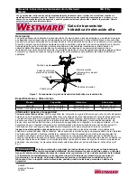
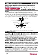
Refer to Figures 1, 2 and 3. Tools Required: 1/2" box
end wrench, 19mm wrench, 3/8" hex socket &
torque wrench.
1. Three major parts are included in package: a)
hydraulic unit with pumping mechanism and air
motor, b) saddle assembly, and c) two pieces of
base half with hardware.
2. Attach either one of the two base halves to the base
of hydraulic unit, then secure with hex socket bolts
and washers provided. Apply the same procedure
to the other base frame. Use torque wrench to
tighten to 30 lb. ft. Do not overtighten.
3. Move the saddle unit above the ram piston, then
place the saddle socket onto the ram piston. Align
the hole and then screw in the hex socket bolt all
the way through.
BEFORE USE
1. Before using this product, read the operator's
manual completely and familiarize yourself
thoroughly with the product, its components and
recognize the hazards associated with its use.
2. Verify that the product and application are
compatible, if in doubt call Westward Technical
Service (888) 332-6419.
3. Press the release valve pedal to ensure that saddle
is fully lowered. Remove shipping screw and
replace with provided vent screw (shipping screw
is located above the oil filler screw).
4. For air option model 5M466C, pour a teaspoon of
good quality, air tool lubricant into the air supply
inlet of the lift control valve. Connect to air supply
and operate for 3 seconds to evenly distribute
lubricant.
NOTICE:
The Model 5M466C is equipped with a
1/4” NPT air coupler. If installing a different air
coupler, use thread tape or compound on all air
connections. To ensure dependable operation,
install an inline air dryer and oiler.
5. Ensure that jack rolls freely. Raise and lower the
unloaded jack throughout the lifting range before
putting into service to ensure the pump operates
smoothly. Replace worn or damaged parts and
assemblies with Omega authorized replacement
parts only.
Venting trapped air procedure
1. Lower saddle to fully lowered position.
2. Unscrew upper set screw, (3 mm). Do not fully
remove, loosen only enough for air to escape.
3. While screw is loose, pump jack slowly, forcing
trapped air past set screw. Continue pumping until
oil begins to exit vent hole.
4. Tighten vent set screw.
5. Pump to maximum saddle height, pump pedal
should not continue to pump with ease when max
height is reached.
6. While lowering saddle, re-release vent screw
checking for oil to exit, not air.
7. Tighten vent screw.
8. If problems persist, repeat steps until all air is
vented.
Operation
Off-center loads and loads lifted while jack is not level
may damage the jack or cause personal injury.
REMOVING TRANSMISSION/DIFFERENTIAL
1. Operate the jack by pressing the lift actuator pedal
or, when pressured air is not available (for Air
Model), operating the foot pedal to desired height.
2. Adjust the saddle in side position and tilting angle
that best fits the shape of transmission/differential.
3. Secure the transmission/differential using nylon
strap and tighten properly.
4. After removing all securing bolts of the transmission/
differential, carefully lower load to jack’s minimum
height. Then move to desired workplace.
INSTALLING TRANSMISSION/DIFFERENTIAL
1. Place transmission/differential on jack saddle and
properly secure by nylon strap.
2. Carefully press the lift actuator pedal (for Air Model)
or operate the pumping pedal if pressured air is not
available to lift the transmission/differential to
desired height.
3. After all fastener bolts are properly secured, press
the release pedal to lower the jack to minimum
height.
Maintenance
NOTICE:
Use premium quality hydraulic jack oil.
Avoid mixing types of oil. Do not use brake fluid,
alcohol, glycerin, detergent motor oil, or dirty oil.
Improper fluid can cause serious internal damage to
the jack rendering it inoperative.


