5/12/2017
TECH-538/D.W.O. 23160
Page 31 of 189
4
Power / Network and Field wiring – Direct Mount
•
The ICoT has been certified for use in hazardous locations to international
standards. Although wiring practices may vary from region to region it is up to the
end user to ensure that the electrical codes for installation have been satisfied.
•
All unused cable entries must be plugged with suitably certified plugs that can
maintain an ingress protection level of IP66.
•
In ambient temperatures below -10
⁰
C and above +60
⁰
C, use field wiring suitable
for both minimum and maximum ambient temperatures
•
Do not over tighten Terminal Screws. Max Torque 3.5 in. lb. /0.4Nm.
ICoT FF Characteristics
ICoT 5400
Connector: J7 (pins 7 and 8)
Grounding: H1 Conn. nut (don’t connect cable
shield)
Operating voltage: 9 to 32 VDC (Max 35 VDC)
Power consumption: 12.5 mA
ICoT 6400:
Connector: J1 (pins 1 and 2)
Grounding: J1 pin 5 (cable shield not connected)
Operating voltage: 9 to 32 VDC (Max 35 VDC)
Power consumption: 12.5 mA
ICoT FF Electrical Connections.
First of all, it’s important to know that The ICoT bus input is polarity
insensitive
. So it doesn’t matter to
which wire is the positive or the negative, provided that they are connected in the BUS A and BUS B
inputs. . The ICoT FF receives both signal and power from the bus so only two wires are necessary
The network wires go through the enclosure conduit entry, use the proper conduit fitting or gland fitting
for IP66 rating and to meet area classification requirements.
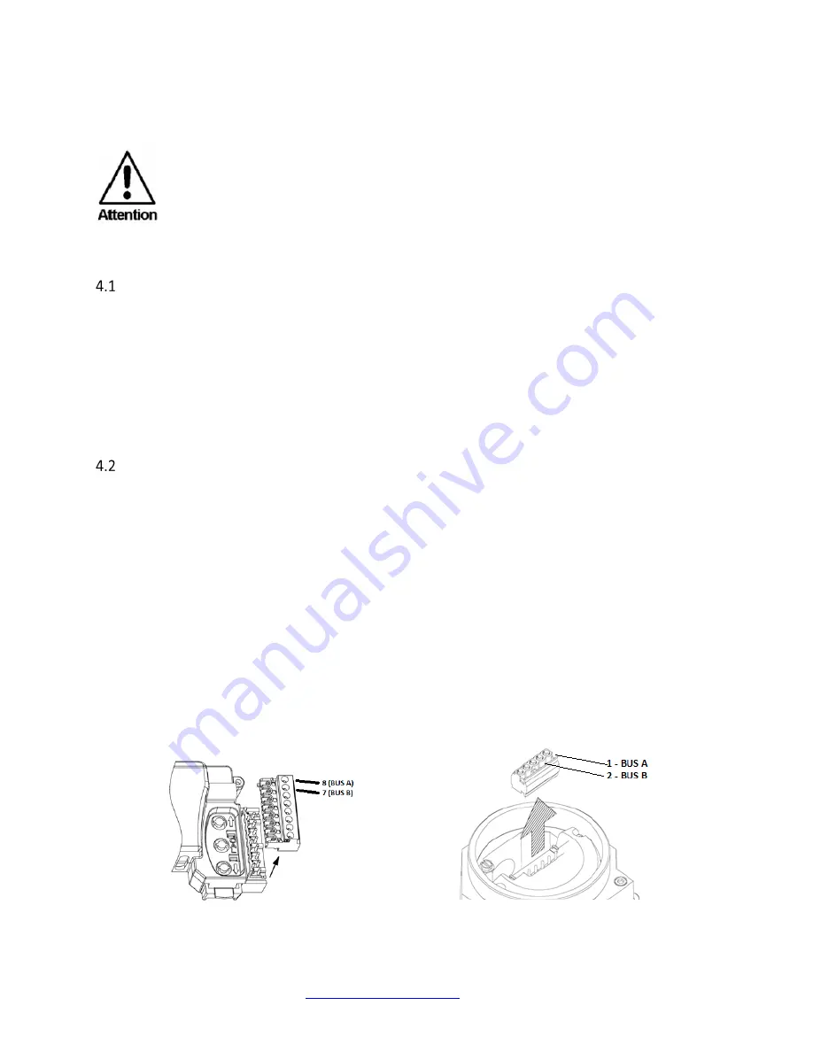
In the ICoT 5400, the two wires coming from the network should be connected in the pins 8 and 7 as
shown in Figure 4-1
In the ICoT 6400, the two wires coming from the network should be connected in the pins 1 and 2 as
shown in Figure 4-2
Figure 4-1 - ICoT 5400 Bus connection pins
(Electrical connection)
Figure 4-2 - ICoT 6400 Bus connection pins
(Electrical connection)


