•
"DB" AIR CIRCUIT BREAKERS
When the series coil current
is
flowing
in
the for
ward direction, armature movement is prevented by
a stop. When the series coil current
is
reversed,
the armature rotates in the opposite direction to
trip the breaker. Calibration adjustment covers
5
to
25
percent reverse current, based on normal
current rating.
After tripping, the reverse current armature is
reset by opening the potential coil circuit. For this
purpose an "a" contact of the breaker auxiliary
switch should be connected in series with the poten
tial coil.
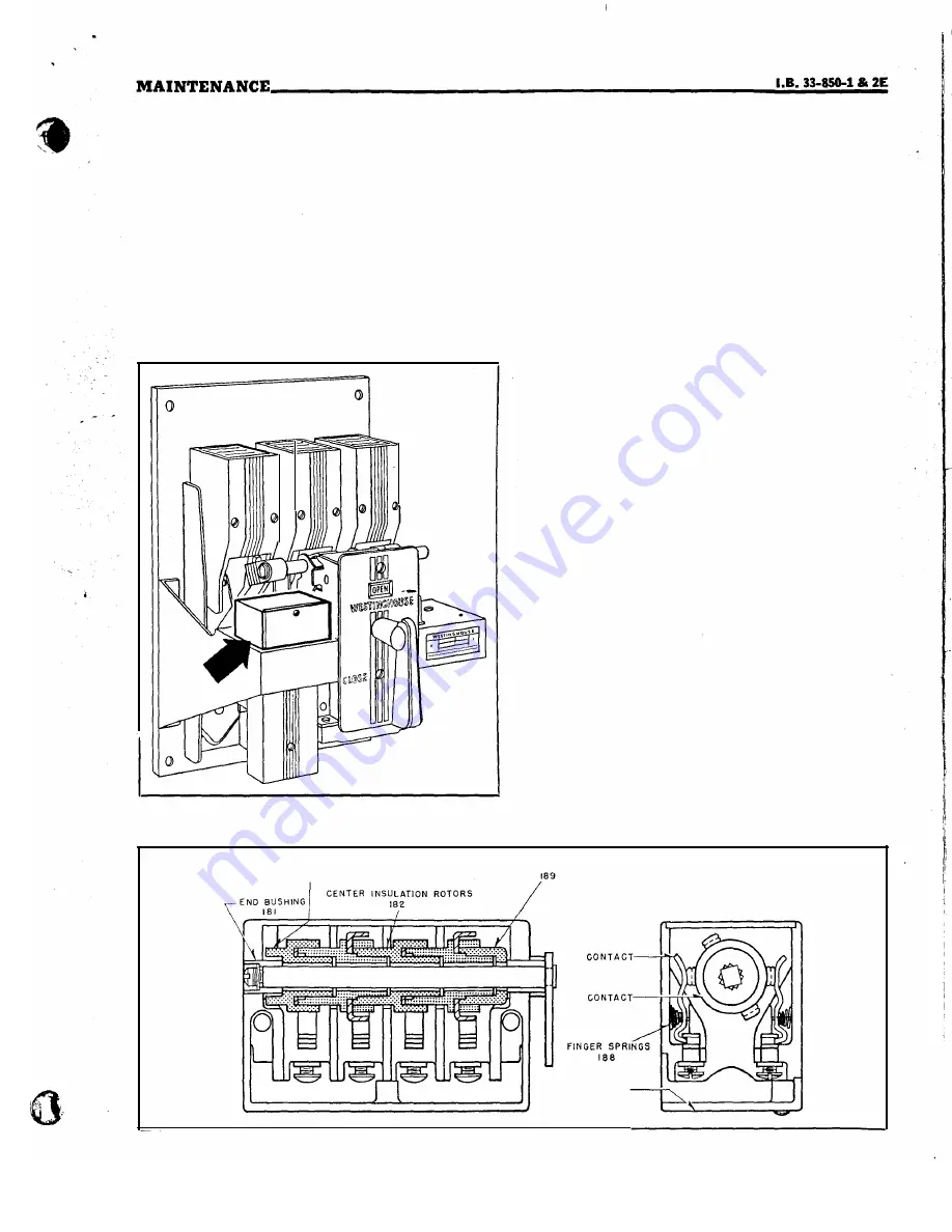
FIG. 15.
Auxiliary Switch-Location
laspection.
Close the breaker manually, and
push backward on the spring stud located on the
bottom of the armature, to trip the breaker. The
armature should move without friction, and should
have approximately 'h2-inch overtravel after trip
ping.
Final inspection should be made electrically, after
the circuit connections are complete as shown in
Fig.
8,
page
22.
�aintenance.
Remove all power from the
breaker and repeat the mechanical inspection given
above. Check for loose bolts and open circuit in
potential coil.
DBF-6 FIELD DISCHARGE SWITCH
The field discharge switch is ordinarily used
with a two-pole breaker, and mounts on the center
moulded pole unit base. (See Fig. 14). The switch
is shipped with the gap setting shown in Fig. 14,
for generator field protection. However, the gap
setting can be reduced to zero or set to open after
the breaker contacts close,
if
desired.
An
arc chute
is always supplied to interrupt motor starling second
ary currents.
Inspection.
Remove the arc chute, close the
breaker manually and check for freedom of motion.
The break distance is adjusted by loosening the lock
nut and turning the sleeve in or out. Always leave
a slight gap at the slop surface.
�aintenance.
Remove power from the break-
•
er, clean the contacts
if
necessary, check the contact
separation and adjust
if
necessary. Check for loose
bolts.
R E A R
I N S U L A T I O N ROTORS
1 8 3
F R O N T I N S U L A T I O N ROTOR
F l N G E R S
1 8 4
R O T O R
1 8 5
FRO N T C O V E R
1 8 6
FIG.
lSA. Auxiliary Switch-Construction Details
29
www
. ElectricalPartManuals
. com
Содержание De-ion DB-15
Страница 24: ...w w w E l e c t r i c a l P a r t M a n u a l s c o m ...
Страница 27: ...w w w E l e c t r i c a l P a r t M a n u a l s c o m ...
Страница 29: ...w w w E l e c t r i c a l P a r t M a n u a l s c o m ...
Страница 31: ...w w w E l e c t r i c a l P a r t M a n u a l s c o m ...
Страница 33: ...w w w E l e c t r i c a l P a r t M a n u a l s c o m ...
Страница 35: ...w w w E l e c t r i c a l P a r t M a n u a l s c o m ...
Страница 37: ...w w w E l e c t r i c a l P a r t M a n u a l s c o m ...
Страница 39: ...w w w E l e c t r i c a l P a r t M a n u a l s c o m ...
Страница 41: ...w w w E l e c t r i c a l P a r t M a n u a l s c o m ...
Страница 43: ... w w w E l e c t r i c a l P a r t M a n u a l s c o m ...


