Содержание De-ion 50-DH-350

Страница 1: ...G AMPERES CONTIN A1R CIRCUIT BREAKER Min KV for Rated uous Max Design At 60 CYCLES TYPE MVA Rated Rated Max Amperes INT KV KV Voltage MVA 4 76 4 0 50 000 50 000 50 DH 350 50 DH 350 350 4 16 1200 48 000 48 000 4 0 4 16 4 76 3000 350 WESTINGHOUSE ELECTRIC CORPORATION SWITCHGEAR APPARATUS DEPARTMENTS EAST PITTSBURGH PA NOVEMBER 1958 EAST PITTSBURGH PLANT NEW INFORMATION Printed in U S A Courtesy of N...

Страница 2: ...Operation Counter Auxiliary Switch Latch Check Switch Undervoltage Trip Attachment Three Coil Trip Attachment Contacts Arc Chutes Levering In Device Test Position Operating Position Interlock Secondary Contacts Puffer Assembly Arc Chute Lifter 8 8 10 10 10 10 10 10 11 11 11 11 11 11 15 15 15 16 16 17 18 INSTALLATION Pari FOOT Pages 19 20 Installation 19 i ADJUSTMENT Part Five Page 21 Mechanism Tri...

Страница 3: ...ationary Arcing Contacts Arc Chutes Broken or Cracked Ceramic Parts Erosion of Ceramics Dirt in Arc Chute Cleaning Arc Shields Operating Mechanism Lubrication Clearances Puffer Puffer Nozzle Organic Insulation 22 22 25 25 25 25 25 25 26 26 1 26 26 27 27 27 PARTS IDENTIFICATION Page 28 Part Seven 28 Parts Identification Renewal Parts 28 i 4 4 I 3 Courtesy of NationalSwitchgear com ...

Страница 4: ...ationary Contact Assembly 8 Arc Chute Arrangement 9 Partially Assembled Arc Chute 10 View of Lower Part of Breaker from Rear 11 Rear View of 3000 Amp 50 DH 350 Breaker 12 Rear View of 1200 Amp 50 DH 350 Breaker 13 Front View Showing Socket for Operating Secondary Contacts 14 Method of Operating Secondary Contacts 15 Pole Unit Assembly 16 Moving Contact Assembly 17 Stationary Contact Assembly 18 Pu...

Страница 5: ...on indicator and levering in device position indicator The arc chutes on this breaker are of the center coil design With this type of construction the magnetic circuit is H shaped with the cross member of the H passing through the center of the arc chute The blowout coils are wound around the cross member of the H and lie in the center of the arc chute With this arrangement the magnet core passing...

Страница 6: ...eel frame with four wheels with roller bearings to facilitate moving the breaker The wheel flanges engage with the rails to align the breaker in the cell The main conductors project horizontally from the rear of the breaker and are supported and insulated by Redarta condenser bushings On the ends of these main conductors are clusters of finger contacts arranged to engage the primary conductors in ...

Страница 7: ... be lifted with slings under the crate If the breaker is to be lifted with slings move it while it is still crated After the breaker is unpacked the best way to move it is by rolling it on its own wheels If it is necessary to lift the breaker after it is incrated lift it without the barrier or arc chutes in place Slings may be placed under the breaker frame or hooks used in the holes provided in t...

Страница 8: ...ving to this position the lower trip free link has disengaged the closing latch The re trieving springs now pull on the solenoid core which moves the linkage to the reset position as shown in Fig 4C In this position the tripping latch is reset and the breaker may be reclosed Before placing the circuit breaker in service it is advantageous to become familiar with the con struction and function of t...

Страница 9: ... 9 and Figure 13 respectively Page 10 Page 9 Page 11 Page 9 Page 13 I B 32 251 3 I B 32 251 4 I B 32 251 6 I B 32 251 9A The rollers rotate on corresponding pins and for trouble free operation of the breakers must rotate very freely without any friction or dragging To insure this the rollers and pins must be lubricated approximately once every year or every 2000 operations The recommended lubrican...

Страница 10: ...I B 32 251 4 Operation 50 DH 350 AIR CIRCUIT BREAKER i i 9 i FIG 4 Solenoid Operating Mechanism 9 Courtesy of NationalSwitchgear com ...

Страница 11: ...er is all the way in or all the way out of the cell Operation Counter The operation counter records each operation of the breaker It advances one count of each tripping operation A link to the trip free lever operates the counter The mechanism panel is mounted on the front of the closing mechanism as shown in Fig 5 On it are mounted the following auxiliary devices included as standard on all break...

Страница 12: ...lays It is bolted between 4 formed copper blades which hinge on the lower bushing foot and form the moving contact arm See Fig 6 All the contact resiliance is built into the sta tionary contact assembly Because of the high momentary rating of the breaker the contacts have been divided to give a multiplicity of contact sur faces See Fig 7 Three sets of arcing and secondary contacts are brazed to ca...

Страница 13: ...OPERATION 1 1 4 FIG 6 Moving Contact Assembly Courtesy of NationalSwitchgear com ...

Страница 14: ...I B 32 251 4 OPERATION 50 DH 350 AIR CIRCUIT BREAKER Courtesy of NationalSwitchgear com ...

Страница 15: ...OPERATION contact contacts part and an arc is drawn it loops up and 14 Courtesy of NationalSwitchgear com ...

Страница 16: ...arc which by this time is two separate arcs extending from the two end arc horns to the transfer horns is driven very rapidly into the slots of the refractory plates As the arc moves to the closed end of the slots it is restricted lengthened cooled and sub ject to a strong magneticly induced blast of gas All of these forces result in rapid deionization of the arc space and for the arc to maintain ...

Страница 17: ...ce operate at right angles to each other When the breaker is closed the mechanism pin is extended over the end of the levering in device pin This prevents the pin from moving and if the pin does not move the coupling cannot be engaged in the levering in device to move the breaker When the The breaker control wiring is arranged for draw out disconnection by means of an 18 point connector block arra...

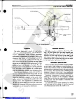
Страница 18: ...ery light the jet of air is released at the instant the breaker is tripped This facilitates the movement of the arc into the arc chute where it is quickly interrupted The arrangement is shown in Fig 18 The diaphragm is connected to the operating mechanism through the two operating rods As the breaker trips open the diaphragm is drawn into the cavity expelling the air which is directed to the conta...

Страница 19: ...e arc chute to the arc chute support casting Next the round bar is placed through the U 2 diameter holes in the front of the arc chutes The two channel members are then connected from the round bar to the rollers on the levering in device arms Then by operating the levering in device in the same man ner as though moving the breaker into the cell the arc chutes can be raised See Fig 3 The full trav...

Страница 20: ...ly and electrically by lifting up on the hand trip assembly on the front of the breaker mechanism panel 6 Close and trip the breaker Close and trip the breaker manually several times to be certain that all parts are functioning properly 7 Connect test jumper Connect the test jumper from the test cabinet to the breaker sec ondary contact block and operate the breaker electrically several times Brea...

Страница 21: ...ts are exposed The breaker should never be rolled into an energized cell structure beyond the test position without the barrier assembly in place 16 Level breaker into cell To move the breaker to the operating position the contacts must be open Place the crank on the levering in device operating shaft press in to engage the levering in device and rotate the crank clockwise to the end of the travel...

Страница 22: ...stud till the proper contact adjustment has been obtained Always be sure to tighten the locking nuts after adjusting the contacts MECHANISM The mechanism in the 50 DH 350 air circuit breaker is adjusted at the factory and is designed to give long trouble free performance Do not make any adjustment unless faulty operation is obsreved Tripping Latch If a breaker fails to close con tacts although the...

Страница 23: ...ined later under Arc Chutes Breakers which have opened large fault currents near the maximum rating should be inspected as soon as practical The con dition of the contact surfaces and the contact pressure adjustment should be checked Also the interior of the arc chutes should be inspected for cleanliness degree of erosion etc For breakers which operate very frequently more maintenance will be requ...

Страница 24: ...I B 32 251 4 Maintenance 50 DH 350 AIR CIRCUIT BREAKER FIG 16 Moving Contact Assembly 23 Courtesy of NationalSwitchgear com ...

Страница 25: ...Bushing 30 Washer 31 Pin 32 Operating Rod 33 Pin 34 Cotter Pin 35 Rod End 36 Lockwasher 37 Left Hand Thread Nut 38 Adjusting Stud 39 Right Hand Thread Nut 1 FIG 17 Stationary Contact Assembly and Parts Identification List 1 Stationary Contact Assembly Complete 2 Cage Casting 3 Clip 4 Insulating Washer 5 Spring Seat 6 Equalizer 7 Arc Contact Spring Inner 8 Arc Contact Spring Outer 9 Insulation 10 S...

Страница 26: ...wer pins and spacers 13 Place Tru Arc rings on lower pin 14 Bolt side plates over upper pin to contact cage casting 15 Bolt top of shunt to contact foot 16 Replace main contact fingers 17 Adjust contacts as described in the section under contact adjustment See Fig 15 ARC CHUTES The insulation parts of the arc chute remain in the circuit across the contacts at all times During the time that the con...

Страница 27: ...ve hand closing lever up and down slowly The core should move freely in the solenoid and the linkage system should reset positively when the weight of the hand close lever is removed slowly Lubrication If any excessive friction or binding is discovered on the above inspection relieve it either by adding oil or if necessary by cleaning old dried lubricant from the bearing surfaces In general the ad...

Страница 28: ...ates Place the new diaphragm in the same position as the one removed and replace the 2 bolts Do not over tighten the bolts so as to crush the diaphragm Place the diaphragm assembly in the cavity of the puffer casting and reconnect the puffer rod to the trip free lever Then replace the 2 castelated nuts Be sure to secure these nuts with the cotter pins Replace the clamping ring using moderate press...

Страница 29: ...ct assembly Figure 17 shows the parts for the stationary contact assembly Figure 18 shows the parts in the puffer assembly Renewal Parts A list of renewal parts recom mended to be kept in stock will be furnished upon request When ordering renewal parts always specify the part name and style identification from the renewal parts data If this is not available identify the part by name from a particu...

Отзывы: