MANUALE UTENTE W-HPT-15K/17K/20K/25K 10
Informazioni sulla messa a terra dei componenti:
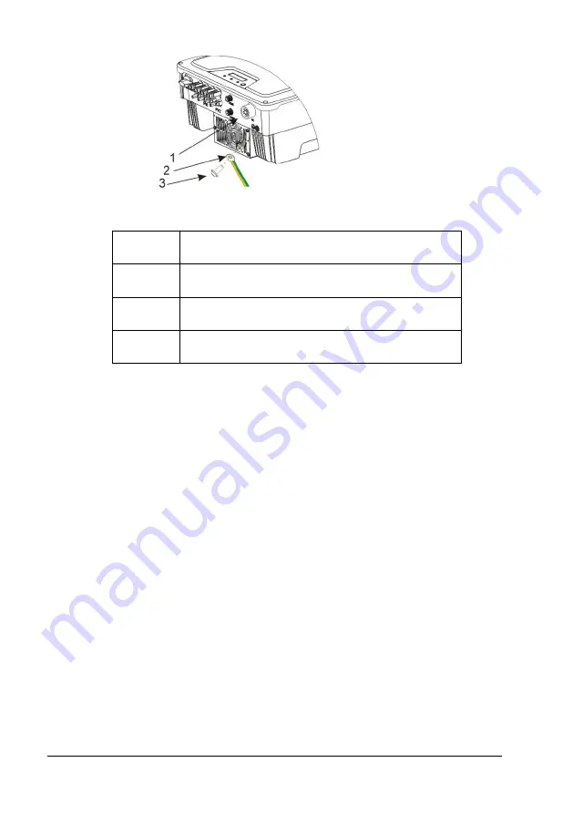
Oggetto
Descrizione
1
Alloggiamento
2
Capocorda con conduttore di protezione
3
Vite a testa piatta M6×12
Sezione trasversale del conduttore PE: 16 mm
²
Страница 1: ...Serie W HPT 15K 17K 20K 25K Inverter solari trifase collegati alla rete MANUALE UTENTE...
Страница 2: ...4 Protezione dalla corrente residua 12 6 COMUNICAZIONE 13 6 1 Monitoraggio dell impianto tramite Wi Fi Stick RS485 Wi Fi GPRS 13 6 2 Controllo della potenza in uscita tramite Contatore Smart 14 6 3 A...
Страница 3: ...LE ALTA TENSIONE EVITARE IL CONTATTO EVITARE OGNI UMIDIT ALTA TEMPERATURA EVITARE IL CONTATTO LIMITE DI IMPILAMENTO IN SEDE DI SPEDIZIONE 7 MARCATURE CE NON SMALTIRE CON I RIFIUTI DOMESTICI PROCEDERE...
Страница 4: ...tovoltaici compatibili con il prodotto 3 In fase di progettazione e fabbricazione di un impianto FV OCCORRE mantenere tutti i componenti nei rispettivi intervalli di funzionamento consentiti e SODDISF...
Страница 5: ...TTORE CA CONNETTOREDEL CONTATORE WI FISTICK DOCUMENTI 1 1 1 4 1 1 1 3 2 Panoramica del prodotto Ledimensioni totali di W HPT 15K 17K 20K 25K sono 425 larghezza 351 altezza 200 profondit mm dotato di 4...
Страница 6: ...postazione sul campo 2 Interruttore CC Per accendere spegnere l inverter 3 Terminali FV Collegato al pannello FV 4 COM1 Wi Fi GPRS RS485 Metodo alternativo di comunicazione a distanza 5 COM2 METRO DRE...
Страница 7: ...e a 45 5 Quando si installa in un ambiente residenziale o domestico si raccomanda di installare e montare l inverter su una superficie solida e in cemento della parete Il montaggio dell inverter su pa...
Страница 8: ...pi di 15 all indietro Montare l inverter su una superficie verticale della parete 4 VIETATO montare l inverter su superfici inclinabili lateralmente o in avanti 5 VIETATO montare l inverter su una su...
Страница 9: ...di calore e assicurarsi che sia fissato in modo stabile 4 Utilizzare viti M5 cacciavite T25 coppia 2 5Nm per fissare le alette del dissipatore di calore alla staffa di montaggio 5 Si raccomanda di ap...
Страница 10: ...PT 15K 17K 20K 25K 10 Informazioni sulla messa a terra dei componenti Oggetto Descrizione 1 Alloggiamento 2 Capocorda con conduttore di protezione 3 Vite a testa piatta M6 12 Sezione trasversale del c...
Страница 11: ...affidabilit di tutti collegamenti di terra deve essere testata e validata 4 Prima della messa in funzione scollegare l inverter e l interruttore automatico o il fusibile onde evitare riaccensioni acci...
Страница 12: ...pi fotovoltaici 5 La polarit dei campi fotovoltaici DEVE essere compatibile con i connettori per CC dell inverter 6 La tensione in ingresso in CC E la corrente in ingresso CC del campo fotovoltaico no...
Страница 13: ...Fi Stick dalla confezione 2 Svitare il tappo della porta COM1 3 Collegare la Wi Fi Stick e stringere Per la guida utente e la configurazione della Wi Fi Stick fare riferimento al corrispondente manua...
Страница 14: ...e CC non sia stata scollegata e scaricata in modo sicuro per evitare scosse elettriche 6 2 Controllo della potenza in uscita tramite Contatore Smart La potenza attiva dell inverter e l efficienza pot...
Страница 15: ...alizzazione Esito poi rilasciare il pulsante per pi di 10s l LCD passer automaticamente a visualizzare il risultato dell auto test Premere brevemente il pulsante per visualizzare gli esiti del test un...
Страница 16: ...lato correttamente e saldamente Controllare che il connettore CA sia saldamente inserito nel terminale CA 6 Cavi Controllare che tutti i cavi siano collegati correttamente Controllare che i collegamen...
Страница 17: ...17 MANUALE UTENTE W HPT 15K 17K 20K 25K 7 2 indicatori LED dell inverter Quando l inverter in funzionamento i simboli LED sul display hanno il seguente significato...
Страница 18: ...T 15K 17K 20K 25K 18 7 3 Logiche di visualizzazione e controllo Quando l inverter si avvia ed in funzionamento compare un pulsante di controllo accanto al display LCD dell inverter Seguire le logiche...
Страница 19: ...e si chiuda involontariamente 3 Usare i morsetti per assicurarsi che non ci sia corrente elettrica nei fili CC 4 Scollegare tutte i collegamenti e le sorgenti CC Scollegare i connettori CC e NON tirar...
Страница 20: ...ghe FV per MPPT 2 Corrente di ritorno massima dell inverter al campo A 0 USCITA CA Potenza nominale W 15000 17000 20000 25000 Potenza apparente CA massima VA 16500 19000 22000 25000 Tensione nominale...
Страница 21: ...ata Protezione da sovracorrente in uscita Integrata Protezione da cortocircuito in uscita Integrata Protezione da sovratensione in uscita Integrata DATI GENERALI Dimensioni L A P mm 425 351 200 Peso k...
Страница 22: ...dell inverter Modalit di risposta della qualit dell alimentazione Funzionamento predefinito per AS NZS 4777 2 2015 Modalit di risposta Volt watt Predefinito Abilitato Modalit di risposta Volt var Pre...
Страница 23: ...ettive 1 Guastofunzionale nell unit microcontrollore MCU L auto controllo ha rilevato un errore dell MCU durante il processo diavvio Scollegare l inverter dalla rete elettrica e dal campofotovoltaicoe...
Страница 24: ...mento di FV e FV verso terra Quando l impedenza d isolamento di rilevamento inferiore a 200kohm viene considerata un guasto d isolamento 1 Se occasionale pu essere causato da unambiente piovoso oumido...
Страница 25: ...llo consentitoa causa delle condizioni della rete locale quindi provare a modificare i valori deilimiti operativi monitorati dopo aver informatoprima la compagnia elettrica Se l anomalia persiste cont...
Страница 26: ...uasto continua adessere visualizzato contattare ilservizio di assistenza 15 Tensione del bus troppo alta La tensione del bus supera 1000V Controllare le tensioni a circuito aperto delle stringhe e ass...
Страница 27: ...zione dell inverter Contenuto Misure di manutenzione Ciclo AVVISO IL DISSIPATORE DI CALORE POTREBBE CAUSARE UN DANNO Quando l inverter in funzione il dissipatore di calore pu superare i 60 Si prega di...
Страница 28: ...onamento Ogni sei mesi Messa in servizio Controllare se i cavi sono allentati Controllare se gli isolamenti dei cavi sono danneggiati in particolare le parti a contatto con superfici metalliche Sei me...
Страница 29: ...Il periodo di durata predefinita di garanzia di anni 10 dalla data riportata nella ricevuta attestante l acquisto del prodotto e in nessun caso pu superare i 63 mesi dalla data di evasione della merce...
Страница 30: ...ivati dal trasporto stesso Si consiglia di tenere l imballo originale La presente garanzia non copre i danni derivati da incuria e negligenza uso errato e improprio del prodotto eventuali danni deriva...
Страница 31: ...ni anticipate o spedizioni a carico Western CO devono essere concordate con l assistenza Western CO e in nessun caso pu essere effettuata una spedizione in porto assegnato non autorizzata Il materiale...
Страница 32: ...W HPT 15K 17K 20K 25K Series 3 Phase Grid tied Solar Inverters USER MANUAL...
Страница 33: ...Wire Assembly and Connection 12 5 4 Residual Current Protection 12 6 COMMUNICATION 13 6 1 System monitoring via WI Fi Stick RS485 Wi Fi GPRS 13 6 2 Output Power Control via Smart Meter 14 6 3 Auto Te...
Страница 34: ...RNING AND CAUTION RECYCLABLE AND REUSABLE HIGH VOLTAGE AVOID CONTACT AVOID DAMP AND MOISTURE HIGH TEMPERATURE AVOID CONTACT SHIPMENT STACK LIMIT 7 CE MARKS DO NOT DISPOSE WITH HOUSEHOLD WASTE PROCEED...
Страница 35: ...rrays MUST not be connected and operate with the product 3 When designing or constructing a PV system all components MUST remain in their permitted operating ranges and their installation requirements...
Страница 36: ...CESSORIES DCPLUGS SEALED ACCONNECTOR METER DRED CONNECTOR WI FISTICK DOCUMENTS 1 1 1 4 1 1 1 3 2 Product Overview The total size of W HPT 15K 17K 20K 25K is 425 width 351 height 200 depth mm It has 4...
Страница 37: ...ting device at field 2 DC Switch For switch on off the inverter 3 PV Terminal s Connected with PV Panel 4 COM1 Wi Fi GPRS RS485 Alternative distant communication method 5 COM2 METER DRED For smart met...
Страница 38: ...e lower than 45 5 When installing in residential or domestic environment it is recommended to install and mount the inverter on a solid concrete wall surface Mounting the inverter on composite or plas...
Страница 39: ...rface over 15 backwards Please mount the inverter on a vertical wall surface 4 DO NOT mount the inverter on any surfaces tilting forward or to both sides 5 DO NOT mount the inverter on a horizontal su...
Страница 40: ...t sink to ensure its stably attached 4 Use M5 screws T25 screwdriver torque 2 5 Nm to attach the heat sink fins to the mounting bracket 5 It is recommended to attach the anti theft lock to the inverte...
Страница 41: ...Instructions 1 Measure the frequency and voltage of grid connection and make sure they follow the inverter s grid connection specifications 2 An external circuit breaker on the AC side or a fuse at 1...
Страница 42: ...1 AC Commissioning 5 2 2 AC Switch Types Please install an individual 2 stage miniature circuit breaker according to the following specifications Model Maximum output current A AC Breaker Rated curre...
Страница 43: ...onnection of PV arrays 5 The polarity of the PV arrays MUST be compatible to the DC connectors of the inverter 6 The DC input voltage AND DC input current of the PV array MUST never exceed the maximum...
Страница 44: ...Wi Fi Stick from package 1 Unscrew the cap in COM1 port 2 Plug the Wi Fi Stick in and tighten For user guidance and configuration of Wi Fi Stick please refer to the corresponding Wi Fi Stick Guide ma...
Страница 45: ...until AC and DC power is securely disconnected and discharged to prevent electric shocks 6 2 Output Power Control via Smart Meter The inverter s active power output and efficiency could be monitored v...
Страница 46: ...lay interface then release the button for more than 10s LCD will automatically switch to display the result of auto test and short press button to display test result one by one 3 Auto test begin afte...
Страница 47: ...C side and if the AC connector is properly and securely installed Check if the AC connector is firmly plugged into AC terminal 6 Cables Check if all cables are reliably connected Check if the connecti...
Страница 48: ...17 HPT 15K 17K 20K 25K USER MANUAL 7 2 Inverter LED Indicators When the inverter operates LED symbols on display have the following meanings...
Страница 49: ...Pac xxxxxW Fac xx xxHz Pac xxxxxW Ver V1 0 0 00 Pac xxxxxW Set Safety Pac xxxxxW Safety Type AS 4777 4 Set Language Pac xxxxxW Language Select English Set Modbus Addr Pac xxxxxW Modbus Addr x Wait sy...
Страница 50: ...switch and prevent the switch from closing unintentionally 3 Use clamps to ensure there is no electrical current in DC wires 4 Disconnect all DC connections and resources Unplug the DC connectors and...
Страница 51: ...d current to the array A 0 OUTPUT AC Rated Power W 15000 17000 20000 25000 Max apparent AC power VA 16500 19000 22000 25000 Rated grid voltage Vac 380 400 Rated power frequency HZ 50 60 Max output cur...
Страница 52: ...ons W H D mm 425 351 200 Weight kg 20 Noise emission typical dB A 45 User Interface LED LCD or LED DC connection type D4 MC4 H4 optional AC connection type Plug in Connector Communication RS485 WiFi G...
Страница 53: ...17K 20K 25K USER MANUAL 22 Volt var response mode Default Disabled Fixed power factor mode Default Disabled Reactive power mode Default Disabled Characteristic power factor curve for cos P Default Di...
Страница 54: ...y current sensor detected AC current sensor detect current abnormal in the start process Disconnect the inverter from the utility grid and the PV array and reconnect it after LED turns off If this fau...
Страница 55: ...g connection of the inverter is reliable If all above are normal please contact the service 7 Ground fault circuit interrupter GFCI exceeds the permissible range residual current over the permission r...
Страница 56: ...settings are normal 11 Grid frequency exceeds the permissible range grid frequency exceeds the Safety regulations If it happens occasionally it belongs to the short time abnormality of the power grid...
Страница 57: ...maximum DC input voltage of the inverter If the input voltage lies within the permissible range while the fault occurs please contact the service 16 Bus voltage too low Bus voltage is 20V lower than s...
Страница 58: ...the parameters are normal during operation Half a year Commissioning Check if the cables are loose Check if the cable insulations are damaged especially the parts in contact with metal surfaces Half a...
Страница 59: ...Section 6 when applicable e g DC Wires need to be reassembled Please run safety checks as described in Section 7 before closing the DC Switch and starting up again 13 CERTIFICATES Grid Standards EN505...
Страница 60: ...his link https www western it en contacts Warranty terms and conditions This warranty covers faults in those products that can be proven to be a material and or factory defect The product will be repa...
Страница 61: ...be assigned to the regenerated device At the end of the warranty period 10 years or the termination of one of the causes that give the right to the warranty itself the assistance will take place with...
Страница 62: ...S r l will be promptly communicated to the Customer The method of resolving the complaint is at the sole discretion of Western CO S r l In case of device out of warranty Western CO S r l will issue a...