background image

Содержание BTA 12.5 KW 60Hz

Страница 1: ...ON GUIDE WESTERBEKE CORPORATION DIESEL GENERATORS SINGLE AND THREE PHASE MODEL BTD 8 0 KW 10 0 KW 11 0 KW BTD A 12 5 KW 60 HERTZ MODEL BTD 6 0 KW 7 5 KW 8 3 KW BTD A 9 4 KW 50 HERTZ Publication 036746...

Страница 2: ......

Страница 3: ...ck Shut off electric power before accessing electrical equipment Use insulated mats whenever working on electrical equipment Make sure your clothing is dry not damp particularly shoes and keep your sk...

Страница 4: ...ow an open flame near the battery being serviced Shut off all electrical equipment in the vicinity to prevent electrical arcing during servicing Avoid Moving Parts Do not service the unit while it is...

Страница 5: ...the equipment at a high level of efficiency and expect dependable performance and long service life in return Should your unit require special attention contact your Westerbeke dealer for assistance...

Страница 6: ...ufacturers with their own software and Westerbeke must depend on such software for the design of Westerbeke s own product software Such software may be outdated and no longer accurate Routine changes...

Страница 7: ...22 BTD 12 5 KW MARINE DIESEL GENERATOR SET GENERAL SPECIFICATIONS 25 SYSTEM SPECIFICATIONS 26 BIDA 12 5 KW MARINE DIESEL GENERATOR SET GENERAL SPECIFICATIONS 29 SYSTEM SPECIFICATIONS 30 INSTALLATION...

Страница 8: ...TABLE OF CONTENTS CONTINUED TABLE OF STANDARD HARDWARE TIGHTENING TORQUES 92 SOUND GUARD INSTALLATION INSTRUCTIONS 94 POWER TAKE OFF PTO ADAPTER KlTS 95 WESTERBEKE GENERATORS 6...

Страница 9: ...W Generator Preheat Solenoid Fuel Lift Pump Fresh Water Fill Oil Pressure Sender 8 0 KW BTD xhaust Manifold Intake Silencer Charging Alternator Fuel Run Solenoid Switch Zinc Anode __ I x h ge Fresh Wa...

Страница 10: ...r Pump Heat Exchanger WESTERBEKE GENERATORS BTD 10 0 KW Generator Preheat Solenoid Intake Silencer 10 0 KW BTD Emergency Shut ide Oil Fill DC Charging rnatar Run __ 4 nc Anode Heat Exchanger Exchanger...

Страница 11: ...or Fresh Water Slock Lube Oil Dip stick Lube Oil Filter 11 0KW BTD Fresh Water Air Heat Exc hang 11 0 KW BTD 9 Water Air Bleed DC Charging Pressure Sender Fitter Shut off Switch Exhaust Temperature Sw...

Страница 12: ...2 5 KW BTD Fresh Water Air Bleed Top Engine Oil Fill Fresh Water I Fill Thermostat Heat Exchanger Sea Water Pump Fresh Water Block Drain Lube Oil Dipstick WESTERBEKE GENERATORS 10 DC Charging i Pressu...

Страница 13: ...___ A C Connections Outlet Fresh Water Block Drain Preheat Solenoid Air Intake Silencer Side Oil Fill I DC Charging Alternator Fuel Lift Pump Oil Pressure Sender 12 5 BTDA RIGHT SIDE Fuel Filter Fuel...

Страница 14: ...Cap Exhaust Manifold Belt Guard Raw Water Pump Heat Exchanger Lube Oil Fill Cap 12 5 BTDA LEFT SIDE Emergency Shut off Switch Exhaust Temperature Switch 45 0 Exhaust Elbow Unit Data Tag DC Battery Gro...

Страница 15: ...cifically for diesel engines The diesel engine does differ form the gasonline engine however in its method of handling and firing of fuel The carburetor and ignition systems are done away with and in...

Страница 16: ...nism 14 hp at 1800 rpms maximum Mechanical centrifugal weight type Swirl chamber type 2 87 x 3 07 inches 73 x 78 mm 60 cubic inches 0 979 liters 1 3 2 Clockwise when viewed from the front 41 50 Ib ft...

Страница 17: ...ding No 2 Diesel oil cetane rating of 45 or higher Nippon Denso Bosch M type 19 BIDC D 5 static timing Throttle type Pintle type 12 Volt DC Electro Magnetic type Canister type with replaceable element...

Страница 18: ...alternator Glow Plug sheathed type 12 volt 1 2 KW reduction type solenoid mounted 90 Amp max at 11 5 Volts 175 200 Amps engine cold Brushless four pole revolving field Pre lubricated single bearing de...

Страница 19: ...STION AIR REQUIREMENTS 60 Hertz AT 1800 rpm ENGINE COMPARTMENT COOLING AIR TUNE UP SPECIFICA TlONS INJECTOR PRESSURE ENGINE TIMING 32 cfm 906 cmm 100 200 cfm 2 83 5 66 cmm 1707 psi 120 kg cm2 10 kg cm...

Страница 20: ...echanism 16 5 hp at 1800 rpms maximum Mechanical centrifugal weight type Swirl chamber type 3 07 x 3 07 inches 78 x 78 mm 68 cubic inches 1 12 liters 1 3 2 Clockwise when viewed from the front 47 7Ib...

Страница 21: ...esel oil cetane rating of 45 or higher Nippon Denso Bosch M Type 19 BIDC O 5 static timing Throttle type Pintle type 12 Volt DC Electro Magnetic type Canister type with replaceable element Metal scree...

Страница 22: ...rnator Glow Plug sheathed type 12 volt 1 6 KW reduction type solenoid mounted 90 Amp max at ll 5 Volts 175 200 Amps engine cold Brushless four pole revolving field Pre lubricated single bearing design...

Страница 23: ...E TIMING Brushless six pole revolving field Sealed lubricated single bearing design 12 Lead reconnectable for low voltage WYE high voltage Delta Solid State voltage regulator with protection circuitry...

Страница 24: ...hanism 18 4 hp at 1800 rpms maximum Mechanical centrifugal weight type Swirl chamber type 2 87 x 3 07 inches 73 x 78 mm 80 cubic inches 1 305 liters 1 3 4 2 Clockwise when viewed from the front 54 Ib...

Страница 25: ...el oil cetane rating of 45 or higher Nippon Denso Bosch M type 19 BIDC O 5 static timing Throttle type Pintle type 12 Volt DC Electro Magnetic type Canister type with replaceable element Metal screen...

Страница 26: ...rnator Glow Plug sheathed type 12 volt 1 6 KW reduction type solenoid mounted 90 Amp max at 11 5 Volts 175 200 Amps engine cold Brushless four pole revolving field Pre lubricated single bearing design...

Страница 27: ...NE TIMING Brushless six pole revolving field Sealed lubricated single bearing design 12 Lead reconnectable for low voltage WYE high voltage Delta Solid State voltage regulator with protection circuitr...

Страница 28: ...chanism 23 hp at 1800 rpms maximum Mechanical centrifugal weight type Swirl chamber type 3 07 x 3 07 inches 78 x 78 mm 91 cubic inches 1 49 liters 1 3 4 2 Clockwise when viewed from the front 67 Ib ft...

Страница 29: ...cetane rating of 45 or higher Nippon Denso Bosch M type 19 BIDC O 5 static timing Throttle type Pintle type 12 Volt DC Electro Magnetic type Canister type with replaceable element Metal screen type cl...

Страница 30: ...alternator Glow Plug sheathed type 12 volt 1 6 KW reduction type solenoid mounted 90 Amp max at 11 5 Volts 175 200 Amps engine cold Brushless four pole revolving field Pre lubricated single bearing de...

Страница 31: ...ENGINE TIMING Brushless six pole revolving field Sealed lubricated single bearing design 12 Lead reconnectable for low voltage WYE high voltage Delta Solid State voltage regulator with protection circ...

Страница 32: ...echanism 23 hp at 1800 rpms maximum Mechanical centrifugal weight type Swirl chamber type 3 07 x 3 07 inches 78 x 78 mm 91 cubic inches 1 49 liters 1 3 4 2 Clockwise when viewed from the front 67 Ib f...

Страница 33: ...ting of 45 or higher Nippon Denso Bosch M type 19 BIDC O 5 static timing Throttle type Pintle type 12 Volt DC Electro Magnetic type Canister type with replaceable element Metal screen type cleanable 4...

Страница 34: ...lternator Glow Plug sheathed type 12 volt 1 6 KW reduction type solenoid mounted 90 Amp max at 11 5 Volts 175 200 Amps engine cold Brushless four pole revolving field Pre lubricated single bearing des...

Страница 35: ...E ENGINE TIMlNG Brushless six pole revolving field Sealed lubricated single bearing design 12 Lead reconnectable for low voltage WYE high voltage Delta Solid State voltage regulator with protection ci...

Страница 36: ...and safe operating conditions for the personnel on board Proper location and installation of the generator set in the vessel are ofprime importance Factors in the installation that must be considered...

Страница 37: ...a water supply to the exhaust must be configured to prevent the siphoning of sea water into the exhaust through the sea water cooling circuit and to prevent the entry of sea water into the exhaust thr...

Страница 38: ...nward to the thru hull discharge This routing will prevent sea water from entering if the thru hull discharge fitting becomes submerged when the vessel heels or rolls while underway or is subjected to...

Страница 39: ...the discharge end secured by a bracket at the front of the engine Oil may be drained from this hose by removing the cap and the discharge end of the hose from the support bracket and lowering the hos...

Страница 40: ...switch s sensor indicate an excessive exhaust temperature an inadequate supply of sea water coolant causes high exhaust temperatures This switch opens at 2600 2700 F 127 1320 C This switch resets at 1...

Страница 41: ...ons Fuel System The generator must have its own fuel supply in other words it must have its own pickup tube and primary filter water separator DO NOT tee off another engine s fuel supply The fuel syst...

Страница 42: ...rolyte level wear rubber gloves a rubber apron and eye protection Battery acid may splash on the skin or into the eyes inadvertently when removing electrolyte caps Check the battery s electrolyte leve...

Страница 43: ...recovery tank should be mounted at manifold level or above c Coolant should be added to the plastic recovery tank after the engine has been filled and started After its operating temperature has been...

Страница 44: ...ture and oil pressure gauge indicators to return to zero deflect to the left of the gauge The DC voltmeter will register system voltage The electron on engine fuel pump glow plugs and fuel run solenoi...

Страница 45: ...through the sea water cooling system during cranking This sea water can enter the engine s cylinders by way of the exhaust manifold once the exhaust system fills Prevent this from happening by closing...

Страница 46: ...ded Check to ensure that there is sufficient fuel in the tank and examine the filter separator bowls for contaminants Clean and drain the bowls as needed Start the generator following the procedure gi...

Страница 47: ...ump engine filter and injection equip ment The owner operator is responsible for making certain the fuel reaching the engine s injection equipment is free of impurities This process is accomplished by...

Страница 48: ...n board at all times Select the parts for your engine from the Parts List and purchase spares from your local Westerbeke Dealer or Distributor For example fuel filter kit 30200 includes replacement el...

Страница 49: ...the only adjustments the servicing dealer can perform on the injection pump Other types of adjustments or repairs must be performed by a qualified injection service shop Typical Fuel System To obtain...

Страница 50: ...d in the engine s 12 Volt DC control circuit is 90 125 Ampere Hours minimum for the generator sets covered by this manual II CAUTION II When quick charging the battery with an external charger be sure...

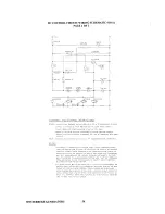
Страница 51: ...TEMP SWITCIi O l RED TEMF _ a TEMP SENDER a o SWITCH 1 r UEL SJLENOID CIRCUIT BREAKER o pj lEHEAT SOLENOID GgJ CIRCUIT 0 SREAKER GROUN I TO I ENGINE BLOCK ffi o RED O HT e 140RN 4 VEL I 1 0 0 OIL PRE...

Страница 52: ...SCURCE OF ClJRRE T AS POSSIBLE EXCESSIVE C0I RE1 Dflr w ANYWHU I TilE I STP UME lT PANE NlRI G OR r GINE W LL cr USE THE BREAKER ro TRIP Ir THIS EVENT OS ENERATORS WILL SI t T owr BE CIIUSE THE OPENED...

Страница 53: ...ing Voltage Test 1 Using a voltmeter connect the voltmeter s red wire clip to the B output terminal on the alternator Refer to the schematic shown above 2 Connect the other voltmeter wire clip to a gr...

Страница 54: ...rough the thermostat into the exhaust manifold then to the heat exchanger where it is cooled and then is returned to the engine block through the suction side of the fresh water circulating pump When...

Страница 55: ...A stainless steel mounting bracket is supplied with each kit along with a 30 inch length of clear plastic hose and clamps to connect the hose between the engine s manifold fitting to the hose spud on...

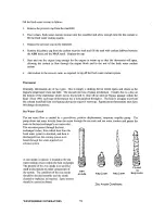
Страница 56: ...f an internal bypass passage within the head Since 1980 each type ofthermostat has a hole punched through it The hole is a bypass to prevent the exhaust manifold from overheating during the engine s w...

Страница 57: ...n with the slot in the drive shaft Move the blades to conform to the curved cam plate and push the impeller into the pump s housing Water Pump Drive Belt Tension Generator models come equipped with be...

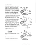
Страница 58: ...Parts List for part numbers and part descriptions ifyou need to order cooling system parts for your engine f WATER ____ _ PRESSURE CAP INJECTED ELBOW __ _ COOLANT RECOVERY TANK INCOMING RAW WATER RAW...

Страница 59: ...ached to the manifold and still be rotated B The exhaust elbow discharge must be directed downward so the mixture of raw water and exhaust gases will flow fall downward into the exhaust muffler which...

Страница 60: ...psi A warmed engine can have an oil pressure reading as low as 35 psi These readings may also vary depending upon the load that is placed on the generator Your generator set is fitted with an oil pres...

Страница 61: ...sterbeke Corporation may vary in size from the original oil filter supplied with the engine i e replacement filter is larger This is due to commonizing of oil filters between engine models The smaller...

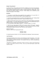
Страница 62: ...leg s 220 Volts at 50 Hertz The no load voltage should be between 118 128 Volts at 61 5 62 Hertz 218 228 Volts at 51 5 52 Hertz NOTE The no load voltage should be adjusted to the voltage produced by t...

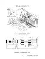
Страница 63: ...l Wiring Schematic for 12 Stud BT Model with Voltage Regulator Circuit Removed r 1 8 JB __ A I iI i t 4 3 I 2 I I I L _____________ J G ORANGE AC BLACK K AC AC r t 1 1 3 3 N 2 A 7 L B B L 7 P I 0 I 3...

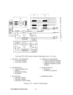
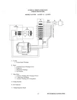
Страница 64: ...A V R Circuit A EXCITER STATOR WINDINGS I Exciter Stator Windings 2 Exciter Stator Windings B EXCITER ROTOR I Auxiliary Windings a b c 2 Diodes 6 3 Rotating Field Windings 4 Pozi Resistor C MAIN STATO...

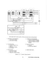
Страница 65: ...r Stator Windings 2 Exciter Stator Windings B EXCITER ROTOR L Auxiliary Windings a b c 2 Diodes 6 3 Rotating Field Windings 4 Pozi Resistor C MAIN STATOR L Main Stator Windings 2 Main Stator Windings...

Страница 66: ...lightly lower than the voltage desired with the regulator in the circuit i e 120 volts 60 Hertz no load voltage in COMP 116 118 volts for 50 Hertz 216 218 volts 4 With the no load voltage adjusted in...

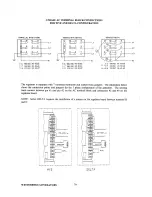
Страница 67: ...V 50Hz 22BV 50Hz 02 sO 50 sO 1r OS 7P Os 3 80 Q3 8 Q I I I H l 1 l 2 AC Voltage Connections 6 Stud Terminal Block Used with the BTD 100KW 11 0KW and the 12 5KW A Generator Sets NOTE The frame ground w...

Страница 68: ...RO Tn n c t U U N L AC Voltage Connections 12 Stud Tenninal Block Used only with the BTD 8 0 KW Generator Set NOTE The frame ground wire must be moved when changing from 110 Volts 50 Hertz to 1220 Vol...

Страница 69: ..._ T __________ J L_I ________ l I I L F REGULATOR A Exciter 1 Exciter Stator Windings B Rotor 1 Auxiliary Exciter Windings a b c 2 Diodes 6 3 Main Rotor Windings 4 Pozi Resistor C Main Stator 1 Auxili...

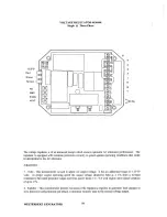
Страница 70: ...djustments I Volts This potentiometer is used to adjust AC output voltage It has an additional range of 25 30 volts At proper engine operating speed the output voltage should be held at 1 from a no lo...

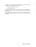
Страница 71: ...se two protection circuits reduces exciter voltage to safegnard the exciter windings and prevent overheating of the AC alternator These two potentiometers are factory adjusted and sealed and should no...

Страница 72: ...3 L2 L3 N 120VAC L L 220VAC 3 L2 L3 N llQVAC 9 5 60 HZ 60 HZ 50 HZ SO HZ The regulator is equipped with 7 uumbered terminals and related brass jumpers The illustration below shows the connection poin...

Страница 73: ...The illustration below shows the 3 phase AC generator backened with the louvered covers removed Voltage Regulator 71 DC Charge Bridge Rectifier AC Terminal Block WESTERBEKE GENERATORS...

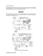
Страница 74: ...to ensure that all AC connections are correct IIOT II U SHOIIS COlirCTIONS FOil 10 N Gl t IIiRE 12 IIOLT SYSTUII fOI TKIH WlltE SYSHIi uS DCllHD tIMES FDa 111 01NU NOl LEGS I I L ____ r I I L G I I I...

Страница 75: ...Volt motors connected medium starting loads will be approximately as follows MOTOR AMPS FOR AMPS FOR SIZE RUNNING STARTING HP Amperes Amperes 1 6 3 2 6 4 to 22 4 114 4 6 9 2 to 32 2 113 S 2 10 4 to 72...

Страница 76: ...le meter and amp probe Preventive Maintenance Generator Maintenance on the generator is minimal 1 Keep the generator clean dry and well ventilated 2 Ensure that all connections are clean and tight and...

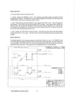
Страница 77: ...h when activated energizes the starter solenoid for starting the engine This switch will not operate electrically unless the PREHEAT switch is depressed and held at the same time 3 STOP The STOP toggl...

Страница 78: ...d and continue to run 3 Stop Depress the STOP switch to stop the engine This opens the power feed to the fuel solenoid stopping the fuel flow to the engine The STOP switch must be held depressed until...

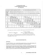
Страница 79: ...71 3 75 36 7 38 3 90 7 3 The voltage drop for Ipecific conductor lengths may be calculated by the formula Voltage drop 10 75 x I x L CM where L CM load in amperes conductor length in feel conductor c...

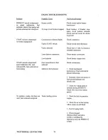
Страница 80: ...TERBEKE GENERATORS 78 VerificationiRemedy Check switch and or battery connections Reset breaker if breaker trips again check preheat solenoid circuit and run circuit for shorts to ground Check connect...

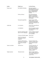
Страница 81: ...ngine by depressing emergency STOP switch on engine or manually moving throttle to shut off Test switch with ohmmeter Depress emergency STOP switch on engine Stop engine by opening the high pressure i...

Страница 82: ...VerificationlRemedv Check wiring Insert sensitive 0 25 Amp meter in battery lines Do not start engine Remove connections and replace after short is located Check all wires for temperature rise to loca...

Страница 83: ...chafed or broken wires loose brackets and fittings damaged hoses loose clamps andother equipment not properly secured 4 Check fuel supply Fill tank s with a good grade of No 2 diesel fuel if required...

Страница 84: ...ngine mounted filter assembly Servicing After Every 500 Hours of Operation I Torque the cylinder head hold down bolts 2 Adjust the valve clearances 3 Drain flush and refill the fresh water cooling sys...

Страница 85: ...ternator for proper operation 4 Check the tightness ofbolts nuts and clamps Servicing After Every 1000 Hours of Olleration 1 Remove clean and pressure test the primary heat exchanger A local automotiv...

Страница 86: ...the timing marks properly if not the valve may be pushed up by the piston depending on position of the cam lobe 3 Next the piston ofNo 3 cylinder comes IDC Turn the crankshaft 2400 clockwise from the...

Страница 87: ...ft timing marks NOTE Retighten the cylinder head bolts before the valve clearance is adjusted BID II OKW BIDA 12 5KW BOLTS 5 6 7 8 9 10 11 12 13 14 I7MM 11 5 12 5 kg m 83 1 86 7 ft Ibs BOLTS 1 2 3 4 I...

Страница 88: ...e delivery valve holder and reattach the fuel line Disconnect the opposite end of the No I fuel line from the No I fuel injector and tum the fitting away from the injector in order to catch the fuel a...

Страница 89: ...II When starting the generator it is recommended that all AC loads especially large motors be switched OFF until the engine has come up to speed and in cold climates starts to warm up This precaution...

Страница 90: ...enoid s operation at the initial start up Periodically lubricated linkage joints between the solenoid plunger and the throttle arm will eliminate binding NOTE The solenoid plunger must move smoothly a...

Страница 91: ...re antifreeze be needed drain an appropriate amount from the engine block and add a more concentrated mixture Operate the engine to ensure a complete circulation and mixture of the antifreeze concentr...

Страница 92: ...eeze mixture should protect the sea water circuit from freezing during the winter lay up as well as providing corrosion protection Remove the impeller from your sea water pump some antifreeze mixture...

Страница 93: ...ust port 2 Remove the sea water pump cover and gasket Discard the gasket Install the sea water pump impeller removed during lay up or a replacement if required Install the sea water pump cover with a...

Страница 94: ...1 7 32 5 3 0 4 5 10 nun bolt head nut 1 5 19 5 30 4 2 7 4 2 12 mm bolt head nut 1 25 ISO 36 2 57 9 5 0 8 0 12 mm bolt head nut 1 5 36 2 50 6 5 0 7 0 12 mm bolt head nut 1 75 34 7 49 2 4 8 6 8 Grade 7T...

Страница 95: ...5 6 0 3 2 3 5 Flywheel bolt with separate 83 2 90 4 SAME SAME washers 11 5 12 5 Flywheel bolt washer 94 0 101 3 SAME SAME attached 13 0 14 0 Oil pan drain plug 36 2 43 4 SAME SAME 5 0 6 0 Oil filter...

Страница 96: ...e Sound Guard installation instructions required for your generator set please contact your local Westerbeke dealer A four page installation brochure is available which covers all current Sound Guard...

Страница 97: ...ate the PTO device simultaneously When mounting a PTO device using the optional adapter kit listed below ensure good alignment of the device to the spline coupling and ensure that if additional suppor...

Страница 98: ......

Отзывы: