


Section 28M-A20-8A0-20A
030-101678 Rev. A
R
0803IARA
4
È
È
È
È
È
È
È
È
È
È
È
È
ÈÈÈÈÈÈÈÈÈ
ÈÈÈÈÈÈÈÈÈ
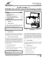
Figure 3.
Exploded View, Showing Compartments Doors/Covers Removed and Showing Mounting Hole Locations
Facility Compartment Cover
Module Compartment
See Note 1
Door
Note 1: Swing-open Customer Cover
removed for visual clarity.
Wall or backboard
Noncombustible
It is not necessary to remove the backplate
28MA208 is shipped fully-assembled:
this view is for visual clarity only.
to mount the assembly.
(remove to expose top mounting holes)
See Paragraph 3.3.1 for mounting details.
sponds with RJ48C/S jack or wirewrap pin connector CKT 8.
When 400-type modules are installed in the mounting, use odd-
numbered slots or circuits. Ventilation/air convection holes at
the top and bottom of the OmniPak
t
8 allow module-produced
heat to escape or dissipate.
2.2.1.2
A ninth module slot is provided in the OmniPak
t
8 for
an optional power supply module. The slot is the right-most slot,
labelled PS" for Power Supply. Route the power supply cable
through the cable access hole at the rear of the slot before insert-
ing the module.
2.2.2
External Power Supply Fuse
When using an external power supply to power the mounting,
a 2 Amp fuse, F1, located in the top Facility Compartment area
next to TB1, is provided to protect the mounting against over-
voltage or power surge.
2.2.3
Ground Lug
Two threaded studs and locking nuts (for optional ground lug
placement) are located at the top of the assembly, under the Fa-
cility Compartment Cover, as shown in Figure 2, as well a third
stud and nut located at the bottom of the assembly under the
Pin Cover Door. The ground lug accepts a #6 AWG copper
ground wire. See Figure 4 and Figure 5 for more wiring details.
- GROUNDING NOTES -
Always follow local safety precautions and standard operating proce-
dures for grounding the equipment when installing, upgrading, or
maintaining equipment. Any instructions or information contained
herein is subordinate to local codes and operating procedures or prac-
tices.
To maintain the UL Listing of these mountings, observe the following
when performing all grounding/bonding connections:
j
Only use conductors containing a like or similar metal type:
do not intermix metals.
j
Any unplated conductor (attached to ground lug) shall be
brought to a bright finish and then coated with an anti-oxi-
dant prior to connection.
j
All grounding/bonding hardware must be listed by an NRTL.
j
#6 AWG copper wire should be used.
2.2.4
Power/Ground Screw Terminal Block
For external power applications, a 3-position screw terminal
block is provided and located under the Facility Compartment
cover for power and ground connections. The left position is la-
PWR-" and is for connection to the +V terminal of
a power supply. The middle position is labelled GND" and is
for connection to earth ground. The right position is labelled
-PWR" and is for connection to the -V terminal of the power
supply. See Figure 4 and Figure 5 for more wiring details for
this terminal block.
2.2.5
Facility Connections
Two types of connectors are available for Facility connections:
either 4-pin wirewrap connectors or 50-pin/25-pair Telco con-
nectors, as described hereunder. Both are located under the
protective Facility Compartment cover (Paragraph 2.1.1) at
the top of the mounting, as shown in Figure 3. Note that the as-
sembly is designed so that this cover cannot be removed unless
the module compartment door is open (a long push-pin slides


