background image

16

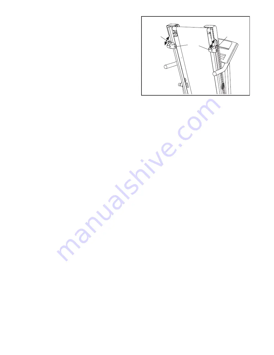
HOW TO CHANGE THE INCLINE OF THE TREADMILL

To vary the intensity of your exercise, you can change

the incline of the treadmill. There are three incline lev-

els.

Before changing the incline, remove the key

and unplug the power cord.

Next, fold the treadmill

to the storage position (see page 17).

To change the incline, first remove the incline pin from

one of the incline legs. Adjust the incline leg to the de-

sired position, and then fully reinsert the incline pin.

Adjust the other incline leg in the same way.

CAUTION:

Before using the treadmill, make sure that both in-

cline legs are at the same height and that both in-

cline pins are fully inserted into the incline legs.

After you have adjusted the incline legs, lower the

treadmill (see page 18).

Incline

Legs

Incline

Pin

Incline

Pin

Содержание Cadence GTX

Страница 1: ...this manual before using this equipment Save this manual for future reference QUESTIONS If you have questions or if parts are damaged or missing PLEASE CONTACT OUR CUSTOMER SERVICE DEPARTMENT DI RECT...

Страница 2: ...23 EXPLODED DRAWING 24 ORDERING REPLACEMENT PARTS Back Cover LIMITED WARRANTY Back Cover WESLO is a registered trademark of ICON IP Inc 2 This drawing shows the location s of the warning decal s If a...

Страница 3: ...eet wearing only stockings or in sandals 11 When connecting the power cord see page 12 plug the power cord into a surge suppressor not included and plug the surge suppressor into a grounded circuit ca...

Страница 4: ...properly tighten all parts of the treadmill regularly 25 Never drop or insert any object into any opening on the treadmill 26 DANGER Always unplug the power cord immediately after use before cleaning...

Страница 5: ...the treadmill If you have questions after read ing this manual please see the front cover of this man ual To help us assist you note the product model number and serial number before contacting us Th...

Страница 6: ...and remove all packing materials do not dispose of the packing materials until assembly is completed Note The underside of the treadmill walking belt is coated with high performance lubricant During...

Страница 7: ...M6 Flat Washers 32 and two M6 Nuts 43 3 52 13 32 32 45 43 13 32 32 45 43 4 Remove the bolts not shown from the indicated holes in the Hood 65 only one side is shown Remove the cardboard packaging and...

Страница 8: ...m Bolt 1 an M10 Flat Washer 14 and an M10 Star Washer 9 do not fully tighten the Bolt yet 5 54 1 1 11 51 14 54 14 9 51 11 11 9 6 Hold the other Frame Spacer 11 between the Left Upright 53 and the Fram...

Страница 9: ...ut of the hole near the bracket on the Right Handrail 7 Console Wire Connector Large Hole 33 Bracket 91 8 Set the Right Handrail 33 on the Console 91 Make sure that the console wire is not pinched Sta...

Страница 10: ...lower the Uprights 53 54 to the floor 11 8 8 8 5 8 5 54 53 9 Have a second person hold the Console 91 near the Right Upright 54 Connect the Wire Harness 39 to the console wire See the inset drawing Th...

Страница 11: ...eg 95 to each side of the Frame 51 with an M8 x 52mm Bolt 82 two M8 Flat Washers 72 and an M8 Nut 46 as shown Note Do not overtighten the Nuts The Incline Legs should be able to rotate easily Adjust t...

Страница 12: ...resistance for electric current to reduce the risk of elec tric shock This product is equipped with a cord having an equipment grounding conductor and a grounding plug Plug the power cord into a surg...

Страница 13: ...center the walking belt if nec essary see page 20 HOW TO TURN ON THE POWER IMPORTANT If the treadmill has been exposed to cold temperatures allow it to warm to room tem perature before turning on the...

Страница 14: ...ck will appear in suc cession until the entire track appears The track will then disappear and the indicators will again begin to appear in succession The center of the track will show the number of l...

Страница 15: ...ne of the displays for a few seconds Each program consists of 30 one minute periods One speed setting is programmed for each period Note The same speed setting may be pro grammed for two or more conse...

Страница 16: ...17 To change the incline first remove the incline pin from one of the incline legs Adjust the incline leg to the de sired position and then fully reinsert the incline pin Adjust the other incline leg...

Страница 17: ...nob make sure that the latch plate is resting against the latch pin To protect the floor or carpet from damage place a mat under the treadmill Keep the treadmill out of di rect sunlight Do not leave t...

Страница 18: ...your left hand pull the latch knob to the left and hold it Next lower the frame until it is past the latch pin Then release the latch knob 2 Hold the frame firmly with both hands and lower it to the f...

Страница 19: ...ROBLEM The power turns off during use SOLUTION a Check the reset off circuit breaker see the drawing above If the circuit breaker has tripped wait for five minutes and then press the switch back in b...

Страница 20: ...off center or slips when walked on SOLUTION a If the walking belt has shifted to the left first re move the key and UNPLUG THE POWER CORD Using the hex key turn the left idler roller bolt clock wise...

Страница 21: ...If your goal is to strengthen your cardiovascular system you must perform aerobic exer cise which is activity that requires large amounts of oxygen for prolonged periods of time For aerobic ex ercise...

Страница 22: ...lles Stretch With one leg in front of the other reach forward and place your hands against a wall Keep your back leg straight and your back foot flat on the floor Bend your front leg lean forward and...

Страница 23: ...y Pan Grommet 50 2 Isolator Fastener 51 1 Frame 52 1 Base 53 1 Left Upright 54 1 Right Upright 55 1 Idler Roller 56 1 Motor Belt 57 1 Electronics Bracket 58 2 18mm Screw 59 1 Motor Bracket 60 1 Left I...

Страница 24: ...8 4 98 93 17 86 51 76 67 28 62 89 3 83 93 6 96 96 31 25 25 25 25 25 75 75 56 25 71 68 28 18 44 95 40 82 46 72 72 95 40 46 82 72 72 27 29 84 74 61 19 55 36 42 84 29 74 60 36 19 42 27 44 19 19 78 50 78...

Страница 25: ...EXPLODED DRAWING B Model No WCTL29509 0 R0609A 34 38 44 79 34 30 59 90 65 47 47 47 57 84 84 42 42 84 84 87 81 66 49 37 99 20 20 20 92 84 25...

Страница 26: ...09A 80 4 54 11 53 14 1 9 1 11 14 9 58 48 39 85 26 63 10 63 26 26 63 33 77 22 88 77 24 70 35 16 63 26 69 69 43 45 32 43 13 5 8 5 8 5 10 10 10 77 63 26 10 10 10 10 35 16 70 69 69 63 26 45 32 43 43 32 13...

Страница 27: ...EXPLODED DRAWING D Model No WCTL29509 0 R0609A 15 91 73 4 12 4 4 4 4 4 4 4 4 4 27...

Страница 28: ...t caused by or attributable to freight damage abuse misuse improper or abnormal usage or repairs not provided by an ICON authorized service center products used for commercial or rental purposes or pr...

Отзывы: