background image

Read This Instruction Manual Carefully Before Using This Equipment.

User Instructions must always be available to the user and are not to be removed except by the user of this equipment. For proper use, see supervisor, 

User Instructions, or contact the manufacturer.

Compliant fall protection and emergency rescue systems help prevent serious injury during fall arrest.  Users and purchasers of this equipment must 

read and understand the User Instructions provided for correct use and care of this product. All users of this equipment must understand the instruc-

tions, operation, limitations and consequences of improper use of this equipment and be properly trained prior to use per OSHA 29 CFR 1910.66 and 

1926.503 or applicable local standards.  

Misuse or failure to follow warnings and instructions may result in serious personal injury or death. 

PURPOSE

The 

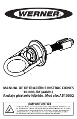
A510002  is an anchorage connector designed to function as an interface between the anchorage and a fall protection, work positioning, rope 

access, or rescue system for the purpose of coupling the system to the anchorage. Any references to “anchorage connector” in this manual include, and 

apply to, the 

A510002.

USE INSTRUCTIONS


1.       Before using a personal fall arrest system, user must be trained in accordance with the requirements of OSHA 29 CFR  


                          1910.66 in the safe use of the system and its components.


2.       Use only with ANSI/OSHA compliant personal fall arrest or restraint systems. The anchorage must have the strength capable                   


          of supporting a static load, applied in the directions permitted by the system, of at least 10,000-lbf (44kN) in the

ural  


                           & operational characteristics of the selected installation location and system to be connected to this anchor. 

Improper use  


            may result in serious personal injury or death.


4.       The anchorage connector must be inspected prior to each use for wear, damage, and other deterioration. If defective 


components are found the anchor connector must be immediately removed from service, in accordance with the requirements    

                           of OSHA 29 CFR 1910.66 and 1926.502.


5.       The complete fall protection system must be planned (including all components, calculating fall clearance, and swing fall)   


                           before using.


6.       A rescue plan, and the means at hand to implement it, must be in place that provides the prompt rescue of users in the    


                           event of a fall, or assures that users are able to rescue themselves.


7.       After a fall occurs, anchorage connector must be removed from service and destroyed immediately.

USE LIMITATIONS


1.       Max Capacity: One user/worker maximum weight of 400-lbs when used as a single point anchorage connector in a fall arrest  


                           system that will limit the maximum arrest force of the user to 1,800-lbf or less. The anchorage connector has a capacity of     


anchorage requirements in  


chorage connector will have a    

                           maximum capacity of one 310-lbs (140kg) user including clothing, tools, etc. when used as part of an ANSI Z359 compliant fall  


                           protection system.


2.       The anchorage connector may be pulled in any direction.


3.       The Anchorage connector is designed to be used in temperatures ranging from -40ºF to +130ºF (-40°C to +54°C).


4.       Do not expose the anchorage connector


5.       Do not alter or modify this product in anyway.


6.       Caution must be taken when using any component of a fall protection, work positioning, rope access, or rescue system near  


                           moving machinery, electrical hazards, sharp edges, or abrasive surfaces, as contact may cause equipment failure, personal   

                           injury, or death.


7.       Do not use/install equipment without proper training by a “competent person” as defined by OSHA 29 CFR 1926.32(f).


8.       Do not remove the labeling from this product.


9.       Additional requirements and limitations may apply depending on anchorage type and fastening option utilized for  


Improper use may result in serious  


                                personal injury or death.

COMPATIBILITY LIMITATIONS

All anchor connectors must only be coupled to compatible connectors.  OSHA 29 CFR 1926.502 prohibits snaphooks from being engaged to certain 

objects unless two requirements are met: it must be a locking type snaphook, and it must be “designed for” making such a connection.  “Designed for” 

means that the manufacturer of the snaphook specifically designed the snaphook to be used to connect to the equipment listed.  The following 

connections must be avoided, because they can result in rollout* when a nonlocking snaphook is used:


• Direct connection of a snaphook to horizontal lifeline.


• Two (or more) snaphooks connected to one D-ring.


• Two snaphooks connected to each other.


• A snaphook connected back on its integral lanyard.


• A snaphook connected to a webbing loop or webbing lanyard.


• Improper dimensions of the D-ring, rebar, or other connection point in relation to the snaphook dimensions that would allow the  


                   snaphook keeper to be depressed by a turning motion of the snaphook.

                      *Rollout: A process by which a snaphook or carabiner unintentionally disengages from another connector or object to which it is coupled.  
 

    (ANSI Z359.1-2007)

MAINTENANCE, CLEANING AND STORAGE

Cleaning periodically will prolong the life and proper functioning of the product. The frequency of cleaning should be determined by inspection and by 

 Do not use any corrosive 

chemicals that could damage the product. Wipe all surfaces with a clean dry cloth and hang to dry, or use compressed air. When not in use, store anchor-

age connectors in a cool, dry, clean environment, out of direct sunlight and free of corrosive or other degrading elements.


WARNING

Werner co. / 93 Werner Rd., Greenville, PA 16125 / 1-(888)-523-3371 / www.wernerco.com


Содержание A510002

Страница 1: ... PERSONS USING THIS EQUIPMENT MUST READ AND UNDERSTAND ALL INSTRUCTIONS FAILURE TO DO SO MAY RESULT IN SERIOUS INJURY OR DEATH USERS SHOULD BE FAMILIAR WITH PERTINENT REGULATIONS GOVERNING THIS EQUIPMENT ALL INDIVIDUALS WHO USE THIS PRODUCT MUST BE PROPERLY INSTRUCTED ON HOW TO USE THIS DEVICE V1 2 ...

Страница 2: ... arrest force of the user to 1 800 lbf or less The anchorage connector has a capacity of anchorage requirements in chorage connector will have a maximum capacity of one 310 lbs 140kg user including clothing tools etc when used as part of an ANSI Z359 compliant fall protection system 2 The anchorage connector may be pulled in any direction 3 The Anchorage connector is designed to be used in tempera...

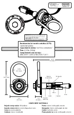
Страница 3: ...injury or death INSPECT BEFORE USE COMPLIANCE OSHA 1910 66 1926 502 ANSI Z359 1 07 Z359 7 11 Tensile Strength UTS 10 000 lbf 44kN Maximum Capacity See Use Limitations Weight 2 0 lbs 949g Regulatory Compliance ANSI Z359 1 2007 ANSI Z359 7 2011 OSHA 1910 66 1926 502 Compression Bushing Polyethylene Retaining Bushing Zinc Plated Steel Cone Stainless Steel Spoons Stainless Steel Bolt Zinc Plated Steel...

Страница 4: ...ight and perpendicular to the surface Make sure the hole is of uniform diameter and free of peaks and valleys on the inner wall See diagram below 2 Blow hole clean with compressed air 3 Refer to the diagram below for hole location and requirements 4 Always inspect the hole carefully when reusing a previously drilled hole LOADING CONDITIONS DIAGRAM ACCEPTABLE ACCEPTABLE IMPROPER ACCEPTABLE LOAD LOA...

Страница 5: ... is below the spoons Insert the anchor into hole so the base plate rest flat on the concrete surface 2 Pull up on the bolt while holding swivel flush with the concrete Tighten the bolt by turning it clockwise by hand until bolt is fastened flush to swivel 3 Use a torque wrench to set the pretension on the bolt for the loading situation required for the application LOAD BOLT TORQUE 85 ft lbs 9 60 N...

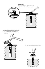
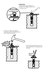
Страница 6: ...9cm Unscrew min of TAP Step 2 Pull UP Step 3 REMOVAL 1 Loosen bolt so that at least 3 4 1 9cm of threads are exposed 2 Use a hammer to tap down bolt and disengage cone from the spoons 3 Pull the anchor from the hole ...

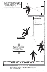
Страница 7: ...hould be removed from service immediately DECK FLOOR GROUND LEVEL WORK SURFACE ANCHOR POINT MINIMUM CLEARANCE 3ft 1m WARNING SWING FALLS CAN OCCUR WHEN THE WORKER IS NOT DIRECTLY UNDER ANCHOR POINT Free fall distance limit must not exceed 6 ft 1 8 m Refer to connecting device documentation for proper usage and limitations The concrete must be 3000 psi or higher and fully cured Installation locatio...

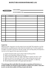
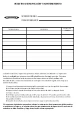
Страница 8: ...ANCE LOG unsafe conditions are found proper disposal is required The anchor connector must be rendered unusable and then properly discarded Date MODEL NUMBER DATE OF MANUFACTURE 1 2 3 Inspect anchoring system for signs of damage or wear to spoons or cone 4 Make sure the unit can rotate 360 5 When reusing a previously drilled hole inspect for for debris or wallowing 6 Record inspection results in t...

Страница 9: ...TILIZAN ESTE EQUIPO DEBEN LEER Y ENTENDER TODAS LAS INSTRUCCIONES NO HACERLO ASÍ PODRÍA RESULTAR EN LESIONES GRAVES O LA MUERTE LOS USUARIOS DEBEN FAMILIARIZARSE CON LAS NORMAS PERTINENTES QUE REGULAN ESTE EQUIPO TODAS LAS PERSONAS QUE UTILIZAN ESTE PRODUCTO DEBEN RECIBIR INSTRUCCIONES APROPIADAS SOBRE CÓMO UTILIZAR ESTE DISPOSITIVO ...

Страница 10: ... capacidad máxima de un 1 usuario de 310 lbs 140 kg incluyendo la ropa herramientas etc cuando se utiliza como parte de un sistema de protección contra caídas que cumple la norma ANSI Z359 2 El conector de ancladero se puede halar en cualquier dirección 3 El conector de ancladero está diseñado para utilizarse en temperaturas que varían desde 40ºF a 130ºF 40 C a 54 C 4 No exponga el conector de anc...

Страница 11: ...idable Cuchara Acero inoxidable Perno Acero enchapado en zinc Manguito Acero enchapado en zinc Cable Cable de avión Pieza giratoria Acero enchapado en zinc COMPONENT MATERIALS ADVERTENCIA Todas las personas que utilizan este equipo deben leer entender y seguir todas las instrucciones No hacerlo así podría resultar en lesiones graves o la muerte INSPECCIONE ANTES DE UTILIZAR CUMPLIMIENTO OSHA 1910 ...

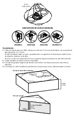
Страница 12: ...orme y está libre de picos y valles en la pared interior Vea el siguiente diagrama de distancia del orificio al borde 2 Limpie soplando el orificio con aire comprimido 3 Consulte el siguiente diagrama de distancia del orificio al borde para ubicación del orificio y requisitos 4 Al reutilizar un orificio taladrado previamente siempre inspeccione cuidadosamente el orificio CONDICIONES DE CARGA DIAGR...

Страница 13: ...sentido horario con sus dedos hasta que el perno quede atornillado todo el recorrido a mano 3 Utilice una llave de torsión llave dinamométrica para aplicar la pretensión del perno para la situación de carga requerida para la aplicación CARGA APRIETE DEL PERNO 85 lbs pie 9 60 Nm 30 lbs pie 3 38 Nm 10 000 lbf 44 kN 5 000 lbf 22 kN Revise en busca de deformación del cono Busque indicios de desgaste e...

Страница 14: ...ínima de 3 4 1 9 cm de roscas 2 Utilice un martillo para golpear hacia abajo el perno y desenganchar el cono fuera de las cucharas 3 El anclaje debe poderse halar hacia afuera del orificio Vea el diagrama de remoción 3 4 1 9cm Destornille un mínimo de GOLPEE SUAVEMENTE Hale hacia arriba ...

Страница 15: ...ivo conector para conocer el uso apropiado y limitaciones El concreto debe tener una resistencia de 3000 psi o superior y estar totalmente curado La ubicación de instalación debe ser aprobada por una persona calificada SUPERFICIE DE TRABAJO Se puede utilizar como punto de anclaje para un sistema de evitamiento de caídas de borde delantero Ejemplos son las ubicaciones de puntos de anclaje opcionale...

Страница 16: ...ondiciones inseguras se requiere desechar apropiadamente el dispositivo El conector de ancladero se debe inutilizar y luego desechar de manera apropiada 1 Inspeccione la pieza giratoria para verificar que está a ras con la superficie de montaje 2 Verifique que las etiquetas están fijadas a la unidad 3 Inspeccione el sistema de anclaje en busca de señales de daño o desgaste de las cucharas o el con...

Отзывы: