background image

7

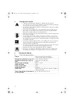
•  The connection to external supply lines must be carried out using a 

screwed cable gland (M20 x 1,5) in the terminal box under the cover (see 
drawings from page 9). Install a fixed connection cable if an unprotected 
or flexible cable is used.

• Turn off the power supply and take steps to ensure against further acciden-

tal use:
- Before connection.
- In the event of damage

• Only operate the appliance when completely assembled. Do not drill into 

or interfere with the explosion-proof housing in any way.

• Observe the nominal voltage (24V DC, stabilised).
• Please note: The application of voltages >26 V will break the zener barrier 

and permanently damage the signal tower.

6

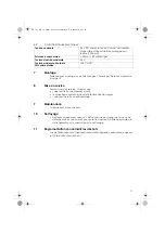
 Technical specifications

6.1

General data

6.2

Electrical Data

7

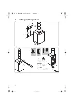
 Mounting

For dimensions and mounting see “Zeichnungen / Drawings / Dessins” 
page 12.

8

 Commissioning

Before commissioning make sure that:
• the appliance has been mounted according to instructions,
• the electrical connections have been carried out correctly,
• the appliance is not damaged in any way.

Material

Housing: Polyester
Dome: Polycarbonate, transparent

Dimensions of the Housing (D x W x H)
Total dimension (D x W x H)

77 mm x 75 mm x 110 mm 
77 mm x 75 mm x 297 mm

Weight

650 g

Temperature range

-20 °C ... +50 °C

Duty cycle

100 %

Protection type according to IEC 60529

IP 65

Installation position

as required

Connection

Screwable connection max. 2.5 mm² incl. 
approved cable gland

Explosion protection

II 2G Ex e mb [ib] IIC T6 Gb

Voltage

24 V DC, only for use with a fused, stabilised 
power supply (T 200 mA).

Current consumption

< 90 mA (< 30 mA/tier)

Maximum input voltage

26 V

Maximum voltage at the fault SELV supply

120 V DC

OFF

NENNSPANNUNG

NOMINAL VOLTAGE

TENSION NOMINALE

310_741_001_14-04.fm  Seite 7  Donnerstag, 17. April 2014  2:56 14

Содержание Ex-LED Signal Tower 741

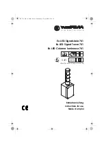
Страница 1: ...Signalsäule 741 Ex LED Signal Tower 741 Ex LED Colonne lumineuse 741 Betriebsanleitung Instructions for use Mode d emploi II 2G ATEX silikonfrei silicone free sans silicone 310_741_001_14 04 fm Seite 1 Donnerstag 17 April 2014 2 56 14 ...

Страница 2: ...nstructions 6 6 Technical specifications 7 7 Mounting 7 8 Commissioning 7 9 Servicing 7 10 Cleaning 8 11 Disposal 8 Sommaire 1 Informations fondamentales 9 2 Description 9 3 Fonctionnement 9 4 Conformité 9 5 Consignes de sécurité 10 6 Données techniques 10 7 Montage 11 8 Mise en service 11 9 Maintenance 11 10 Nettoyage 11 11 Réglementation concernant les déchets 11 12 Zeichnungen Drawings Dessins ...

Страница 3: ...die Zündschutzarten Vergusskapselung mb Eigensicherheit ib und Erhöhte Sicherheit eb im Anschlussbereich erreicht 4 Konformität Das Gerät entspricht folgenden Normen und Richtlinien Richtlinie 94 9 EG ATEX 2004 108 EG EMV EN 60079 0 EN 60079 7 EN 60079 11 EN 60079 18 EN 60947 5 1 5 Sicherheitshinweise Das Gerät ist ausschließlich zur bestimmungsgemäßen Verwendung wie unter Funktion beschrieben vor...

Страница 4: ...tsmäßig montiert wurde der elektrische Anschluss ordnungsgemäß ausgeführt wurde das Gerät nicht beschädigt ist Material Gehäuse Polyester duroplastisch Kalotte Polycarbonat transparent Maße des Gehäuses L x B x H Gesamtabmessungen L x B x H 77 mm x 75 mm x 110 mm 77 mm x 75 mm x 297 mm Gewicht 650 g Einsatz Temperaturbereich 20 C 50 C Einschaltdauer ED 100 Schutzart nach IEC 60529 IP 65 Montagelag...

Страница 5: ...sser oder milde nicht scheuernde nicht kratzende Reinigungsmittel verwenden Niemals aggres sive Reinigungsmittel oder Lösungsmittel verwenden 11 Entsorgung Bei der Entsorgung sind die nationalen Abfallbeseitigungsvorschriften zu beachten 310_741_001_14 04 fm Seite 5 Donnerstag 17 April 2014 2 56 14 ...

Страница 6: ...hazardous areas where flammable gas or vapours are present The device group II cate gory 2G permits use in potentially explosive atmospheres of zones 1 and 2 The gas explosion protection is achieved by casting compound protection mb intrinsic safety ib and increased safety eb in the area of the electrical con nection 4 Conformity The appliance meets the following standards and directives Directive...

Страница 7: ...ichnungen Drawings Dessins page 12 8 Commissioning Before commissioning make sure that the appliance has been mounted according to instructions the electrical connections have been carried out correctly the appliance is not damaged in any way Material Housing Polyester Dome Polycarbonate transparent Dimensions of the Housing D x W x H Total dimension D x W x H 77 mm x 75 mm x 110 mm 77 mm x 75 mm ...

Страница 8: ...damp cloth using water or mild non chafing non scratching cleaning fluid Never use aggressive substances or solvents when cleaning 11 Disposal Observe national waste disposal regulations when disposing of the appliance 310_741_001_14 04 fm Seite 8 Donnerstag 17 April 2014 2 56 14 ...

Страница 9: ...pose d un boîtier de connexion en plastique thermodurcissable et d éléments optiques en polycarbonate Les différents étages peuvent être connectés et déclenchés depuis le boîtier de conne xion Merci de veiller à respecter la polarité lors du câblage 3 Fonctionnement L appareil a été conçu pour l alarme l appel et la signalisation dans des zones explosibles dont le danger est d origine gazeuse Le g...

Страница 10: ...ut de celui ci couper la tension du réseau Prendre des mesures de sécurité pour éviter toute remise en marche accidentelle N employer l appareil que lorsqu il est complètement monté Des forures ou des manipulations au boîtier antidéflagrant sont à éviter Respecter la tension nominale indiquée 24V DC stabilisée Important une tension d alimentation supérieure à 26 V entraînera des dommages irrémédia...

Страница 11: ...tilisant de l eau ou du détergent doux non corrosif pour éviter les rayures N utilisez jamais de pro duits agressifs ou de solvants pour le nettoyage 11 Réglementation concernant les déchets Lors de l élimination de l appareil respecter la législation nationale en vigueur sur l élimination des déchets Tension nominale 24 V DC Alimentation en courant doit résulter d une alimentation stabilisée prot...

Страница 12: ... 45 mm 1 77 109 mm 4 29 98 mm 3 86 74 mm 2 91 IP65 Kabelverschraubung montieren und gut festziehen Mount cable gland and screw tightly into place Monter le passe câble à vis et le visser fermement 5 Nm 310_741_001_14 04 fm Seite 12 Donnerstag 17 April 2014 2 56 14 ...

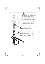
Страница 13: ...ltages 26 V will break the zener barrier and permanently damage the signal tower Une mauvaise polarité au niveau des connecteurs et une tension d alimentation supérieure à 26 V entraînera des dommages irrémédiables sûr la barrière zener et la colonne lumineuse 4x 1 2 IP65 Gerät darf ohne mitgelieferte Dichtung nicht betrieben werden Do not use appliance without seal included in assembly Ne pas fai...

Страница 14: ... ATEX Richtlinie 94 9 EC Equipment and protective systems intended for use in potentially explosive atmospheres ATEX Directive 2004 108 EG EMV Richtlinie 2004 108 EC EMC Directive Dies wird nachgewiesen durch die Einhaltung folgender Normen this is documented by the accordance with the following standards bzw EN 60079 0 2009 bzw EN 60079 7 2007 bzw EN 60079 11 2012 bzw EN 60079 18 2009 bzw 60947 5...

Страница 15: ...15 310_741_001_14 04 fm Seite 15 Donnerstag 17 April 2014 2 56 14 ...

Страница 16: ...16 310_741_001_14 04 fm Seite 16 Donnerstag 17 April 2014 2 56 14 ...

Страница 17: ...17 310_741_001_14 04 fm Seite 17 Donnerstag 17 April 2014 2 56 14 ...

Страница 18: ...18 310_741_001_14 04 fm Seite 18 Donnerstag 17 April 2014 2 56 14 ...

Страница 19: ...19 310_741_001_14 04 fm Seite 19 Donnerstag 17 April 2014 2 56 14 ...

Страница 20: ...fm 17 4 14 www krea team de Technische Änderungen vorbehalten Subject to technical modifications Sous réserve de modifications techniques 310 741 001 0414 D 310_741_001_14 04 fm Seite 20 Donnerstag 17 April 2014 2 56 14 ...
Отзывы: