5
INSTALLATION
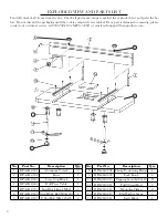
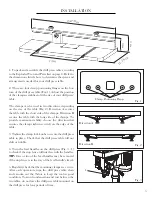
1. Unpack and assemble the drill press table according
to the Exploded View and Parts List on page 4. Refer to
the dimensions listed above to determine the space and
arrangements needed for your drill press table.
2. There are four clamp positioning flanges on the bot-
tom of the drill press table (Fig. 1). Adjust the position
of the clamp assemblies to fit the size of your drill press’
table.
The clamps can be used in two directions, depending
on the size of the table (Fig. 2). Direction A secures
the table with the short side of the clamps. Direction B
secures the table with the long side of the clamps. To
provide maximum stability, choose the direction that
ensures the clamps tighten securely on the edge of the
table.
3. Tighten the clamp lock knobs to secure the drill press
table in place. Check that the drill press table will not
shift or wobble.
4. Turn the feed handles on the drill press (Fig. 3 - 1)
to check if the stop fence will interfere with the handles.
TIP:
One or two of the feed handles may be removed
if the stop fence is in the way of the feed handle’s travel.
5. Regularly check that the mounting clamps are secure.
After each operation, wipe the drill press table clean
and vacuum out the T-slots to keep the tool in good
condition. To avoid condensation and rust between the
two tables, do not leave the drill press table mounted on
the drill press for long periods of time.
Fig. 1
Fig. 2
Fig. 3
Direction A
Direction B
Clamp Positioning Flange
1
11-7/8 in
.
23-7/8 in.
13 in.
4 in
.
5 in
.
Содержание DPA2412
Страница 7: ...THANKS FOR REMEMBERING ...

