ASSEMBLY & ADJUSTMENTS
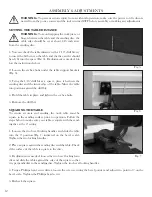
Fig. 4
WORK TABLE ASSEMBLY
1. Holding the table flat, slide it onto the base frame.
2. Thread the pivot indexing pin fully into the pivot hole, through the scale plate. The scale plate should ride along
the outside of the indexing pin head.
3. Insert the bevel locking handle through the flat washer, the scale plate and into the front hole on each side of the
base frame.
NOTE:
The bevel locking handles are threaded and spring-loaded. Pull out the handle to re-position it. Push in
the handle and rotate it to tighten or loosen the table. After tightening the handle, re-position it so that the handle
is pointing downwards, to prevent it from interfering with the work table .
4. Follow the instructions on the next page to properly adjust the work table and miter gauge.
Pivot Indexing Screw
Pivot Hole
Front Hole
Bevel Lock Knob
11
Содержание 65812
Страница 16: ...EXPLODED VIEW PARTS LIST 16 ...
Страница 20: ...THANKS FOR REMEMBERING ...


