background image

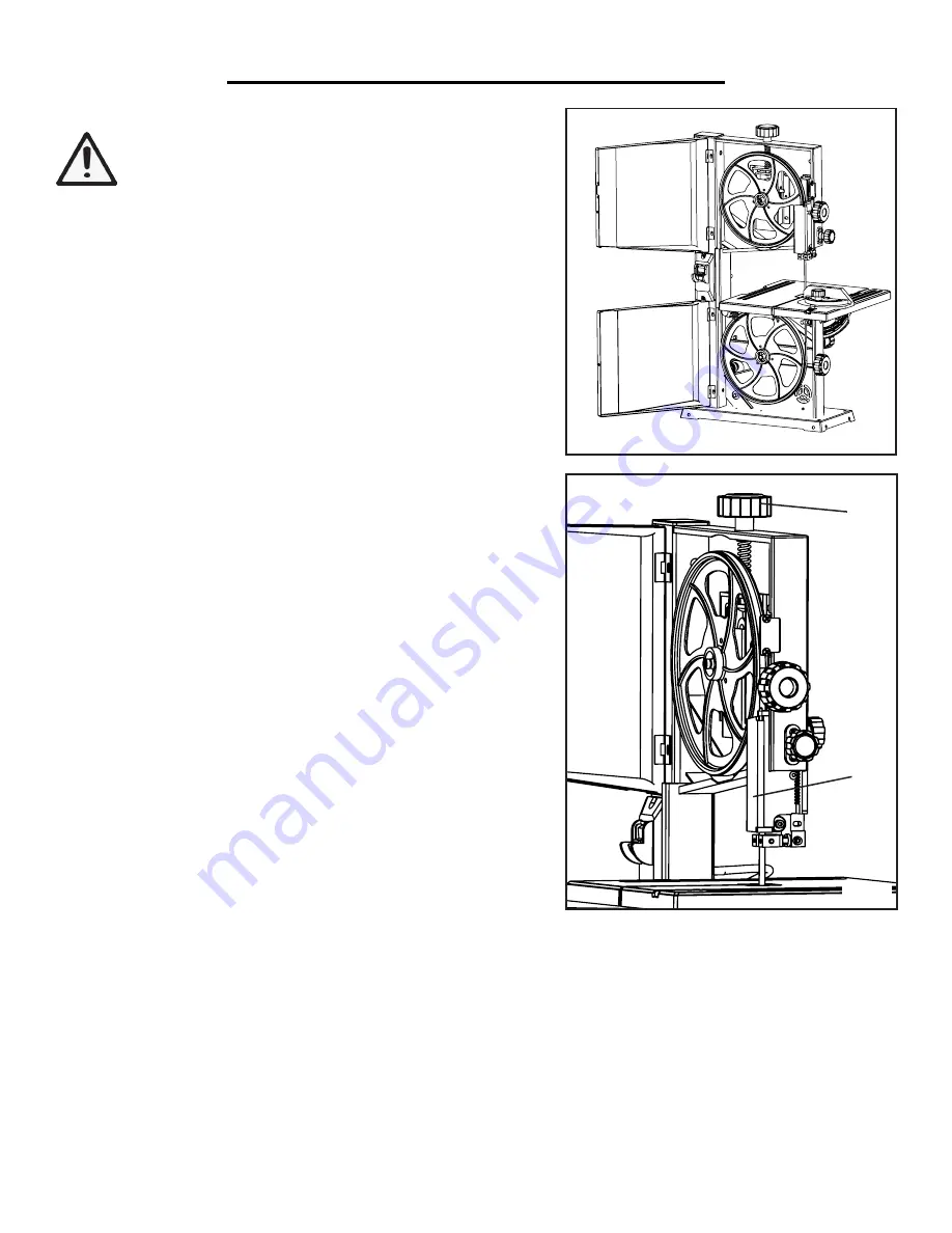
CHANGING THE BAND SAW BLADE (Fig. M & N)

WARNING

: Saw blades can be dangerous. Wear work 

gloves  while  handling  the  blade  or  when  moving  new 
blades from the packaging.

1. Remove the M6X24 hex bolt, spring washer, flat washer and 
wing nut from the work table assembly. 

2. Open the upper and lower blade covers (Fig. M). 

3. Set the upper blade guard to its lowest position, minimizing the 
space between the bottom of the blade guard and the table assem-
bly.

ASSEMBLY & ADJUSTMENT

12

We also made a video that takes you through the steps of installing and adjusting a bandsaw blade. Check it out at:

http://bit.ly/WENbandsaw

4. Open the blade guard cover (Fig. N - 1) by pushing down on 
the top of the cover, and simultaneously pulling it outwards, away 
from the wheel.

5. Loosen the tension knob (Fig. N - 2) until you can remove the 
blade from the machine.

NOTE: Now is a good time to clean out your band saw to ensure 
the best performance. Clear out any sawdust, wood chips, etc. with 
a shop vacuum. Ensure that the wheels and tires are free of saw-
dust and chips. This promotes good wheel balance and good blade 
tracking.

6. Fit the new blade through the guiding slots on both the left and 
right sides of the machine onto the upper and lower rubber tires. 
Position the blade in the center of the rubber tires. Ensure that the 
blade teeth are pointing down towards the table. 

7. Turn the blade tensioning knob clockwise to put the new blade 
under tension. 

8. Close the upper blade guide assembly cover by pushing in until 

Fig. M

1

2

it clicks in place.

9. Replace the M6X24 hex bolt, spring washer, flat washer and wing nut onto the work table assembly. 

10. After every blade change, make sure to follow the instructions on page 10 and 11 to adjust the tracking of the 
blade, the blade tension, and the upper and lower blade guides. Proper tuning of your band saw is necessary to 
ensure optimum performance of the machine. 

11. After all adjustments and tuning are complete, close the upper and lower wheel covers. 

Fig. N

Содержание 3959

Страница 1: ...rformance Pay close attention to the rules for safe operation warnings and cautions If you use your tool properly and for intended purpose you will enjoy years of safe reliable service IMPORTANT NEED HELP CONTACT US Have product questions Need technical support Please feel free to contact us at 800 232 1195 techsupport wenproducts com WENPRODUCTS COM M F 8AM 5PM CST Model 3959 bit ly wenvideo For ...

Страница 2: ...roat Cutting Depth Work Table Size Table Bevel Angle Blade Length Blade Width Dust Port Size Outer Diameter Net Weight Assembled Dimensions 3959 120 V 60 Hz 2 5A 2500 FPM 9 inches 228 mm 3 1 2 inches 89 mm 12 5 16 x 11 7 8 inches 0 to 45 degrees right 59 1 2 inches 1511 mm 1 8 to 3 8 inches 2 1 2 inches 64 mm 40 pounds 19 X 14 X 29 Inches Operation Maintenance 2 Specific Safety Rules For Band Saws...

Страница 3: ...plies periodically Do not use defective cords Damaged or entangled cords increase the risk of electric shock 4 Do not abuse the cord Never use the cord for carrying pulling or unplugging the power tool Keep cord away from heat oil sharp edges or moving parts PERSONAL SAFETY 1 Stay alert Watch what you are doing and use common sense when operating a power tool Do not use a power tool while you are ...

Страница 4: ...isconnect the power cord plug from the electrical outlet when making adjustments changing parts or storing power tools Such preventive safety measures reduce the risk of starting the power tool accidentally 2 Maintain power tools properly Safely store power tools out of the reach of children Always keep tools clean and in good working order Follow instructions for lubricating and changing accessor...

Страница 5: ...he table below shows the correct size to be used according to cord length and nameplate ampere rating When in doubt use a heavier cord The smaller the gauge number the heavier the cord Make sure your extension cord is properly wired and in good condition Always replace a damaged extension cord or have it repaired by a qualified person before using it Protect your extension cords from sharp objects...

Страница 6: ...n t twist rock or slip while being cut Small pieces should be secured with clamps or fixtures Do not hold small pieces with your hand because your fingers might go under the blade guard 9 Use extra caution with very large very small or awkwardly shaped workpieces 10 Plan intricate or small work carefully to avoid pinching the blade Avoid awkward operations and hand positions to prevent accidental ...

Страница 7: ...emove the plug before performing any inspections adjustments and mainte nance Wait for all moving parts to come to a complete stop 22 If any part of this band saw is missing broken bent or damaged in any way or if any electrical component fails to perform properly shut off the power switch remove the machine plug from the power source and have the dam aged missing or failed parts replaced before o...

Страница 8: ...ent Knob Dust Port 2 1 2 O D Blade Guard Lock Knob Upper Blade Guides Upper Housing Knob Lower Housing Knob Blade Tracking Knob Blade Tracking Lock Lever Motor Lower Wheel Adjustment Screws Blade Guard Adjustment Knob Blade Guard Use the graphic below to become familiarized with the different parts and controls of your band saw 8 ...

Страница 9: ...ig D 1 Loosen the two table lock knobs located on the back of the band saw Fig D 1 2 Adjust the table to the desired angle using the angle adjustment knob Fig D 2 and the angle indicator The table can be tilted 45 degrees to the right 3 Use the angle indicator to confirm the desired angle and tighten the table lock knobs NOTE a table perpendicular to the blade corresponds to a scale indication of ...

Страница 10: ...wheel Close and lock the covers NOTE Blade tracking will be more difficult with thinner blades but don t be frustrated Keep at it and you ll get there ADJUSTING THE BLADE TENSION Fig H Proper tensioning of the blade is important before operating the band saw If the tension in the blade is too high it runs the risk of breaking If the tension is too low there is a risk of the blade slip ping and sto...

Страница 11: ...e change or blade tracking adjustment 1 Open the lower wheel cover The table might need to be re moved for easier access to the adjustment screws 2 The procedure is the same as adjusting the upper guides Loos en the lower screw Fig K 2 to adjust the thrust bearing 0 5 mm from the back of the blade Loosen the upper screw Fig K 1 to adjust the side guides 1 2 mm from the teeth of the blade Loosen th...

Страница 12: ...e the best performance Clear out any sawdust wood chips etc with a shop vacuum Ensure that the wheels and tires are free of saw dust and chips This promotes good wheel balance and good blade tracking 6 Fit the new blade through the guiding slots on both the left and right sides of the machine onto the upper and lower rubber tires Position the blade in the center of the rubber tires Ensure that the...

Страница 13: ...tance of the fence to the blade depending on the length you would like to cut Lock it in place by pushing down on the fence lock handle Fig R Make sure the fence is locked down before operation Fig Q Fig R 13 1 SUGGESTIONS AND WARNINGS Do not touch the saw blade when cutting During saw operation wear safety glasses but do not wear gloves Cut only one workpiece at a time Always hold the workpiece d...

Страница 14: ...turn the power on until all adjustments have been made 2 Use the band saw for straight line operations such as cross cutting ripping miter cutting beveling compound cut ting and resawing To avoid twisting the blade do not turn sharp corners instead saw around corners A band saw is not capable of doing intricate inside cutting as can be done with a scroll saw Refer to the Circle Cutting Guide for t...

Страница 15: ...15 EXPLODED VIEW AND PARTS LIST ...

Страница 16: ...er 1 32 3959 032 Cover Spring 1 33 3959 033 Screw 1 34 3959 034 Slide Board 1 No Part No Description Qty 35 3959 035 Upper Guide Slide Bar 1 36 3959 036 Hex Screw M4X4 1 37 3959 037 Pin 5X14 4 38 3959 038 Upper Blade Guide Sup port 1 39 3959 039 Upper Support Shaft 1 40 3959 040 Flat Washer M5 3 41 3959 041 Ball Bearing 2 42 3959 042 Bearing Fastening Screw 2 43 3959 043 Hex Screw M5X10 3 44 3959 ...

Страница 17: ... 3959 092 Butterfly Nut M6 1 93 3959 093 Flat Washer D6 4 94 3959 094 Slide Bar 1 95 3959 095 Miter Gauge Knob 1 96 3959 096 Miter Gauge 1 97 3959 097 Philips Screw Flat Washer Spring Washer As sembly M5X8 1 No Part No Description Qty 98 3959 098 Miter Gauge Pointer 1 99 3959 099 Lower Support Shaft 1 100 3959 100 Lower Blade Guide Sup port 1 101 3959 101 Spring Washer D10 1 102 3959 102 Capacitor...

Страница 18: ...epaid by the purchaser The prod uct must be shipped in its original container or an equivalent properly packed to withstand the hazards of ship ment The product must be fully insured with a copy of the warranty card and or the proof of purchase enclosed There must also be a description of the problem in order to help our repairs department diagnose and fix the issue Repairs will be made and the pr...

Страница 19: ......

Страница 20: ...THANKS FOR REMEMBERING ...

Отзывы: