


BURNER ASSEMBLY INSTRUCTIONS
A. ORIFICE INSTALLATION
1. Slide the brass ORIFICE through the ring on the
end of the BURNER, threaded end pointing out.
2. Slide the ORIFICE WASHER over the threads
of the ORIFICE.
3. Screw the ORIFICE HOLDER on to the ORIFICE.
Tighten the orifice holder so that the compression
fitting sits pointing toward the outside and down at
a 30º angle.
4. Always use a back-up wrench when tightening
the orifice to avoid bending the orifice bracket.
B. SHUTTER ADJUSTMENT
1. This is an initial adjustment. Final adjustment
will be made while the burner is in operation.
2. Loosen the holding screw. Set the shutter so
that 1/8" of the shutter is exposed.
Tighten the screw.
C. BURNER TUBES
1. BURNER TUBES are handed right and left.
Visually, the row of burner slots point up and
slightly inward. Also, the tops of the rear
mounting tabs slant toward the center.
D. IGNITOR ASSEMBLY
1. IGNITORS are handed right and left. Visually:
a.
Right: The flame sensor (right probe) is
bent at a 90º angle;
b.
Left: The flame sensor (right probe) is
nearly straight.
2. When properly assembled, all three probes will
lay on a line drawn from the center of the burner
tube through the center of the burner slots.
3. All three probes should be .5" from the outer
surface of the burner slots.
4. The gap between the ignitor and ground probes
must be .10".
5. To insure proper ignition, the gap between the
ignitor and ground probes must be directly in
the gas stream.
6. To insure proper flame detection, the tip of the
flame sensor probe must be directly in the gas
stream.
14
ORIFICE HOLDER
ORIFICE WASHER
BURNER
ORIFICE
30º
SHUTTER
BACK-UP
WRENCH
Содержание WFGA-60FS
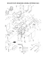
Страница 25: ...23 WFAE 60FS PARTS BREAKDOWN GENERAL REFERENCE ONLY ...
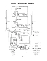
Страница 26: ...24 WFGA 60FS WIRING DIAGRAM SCHEMATIC ...


