1753-27
RP 235
E-LINK
E - LINK
START
STOP
Pr
1729.99.03.02
08.04
from year of manufacture 2004
Operating Manual
Страница 1: ...1753 27 RP 235 E LINK E LINK START STOP START STOP Pr 1729 99 03 02 08 04 from year of manufacture 2004 Operating Manual...
Страница 2: ......
Страница 3: ...NU 23 7 1 OVERVIEW OF THE BUTTON FUNCTIONS IN THE SYSTEMINFO MENU 24 8 DIAGNOSIS MENU 25 8 1 STANDARD DIAGNOSIS 26 8 2 EXTENDED DIAGNOSIS 31 8 3 OVERVIEW OF THE BUTTON FUNCTIONS IN THE DIAGNOSIS MENU...
Страница 4: ...THE SYSTEM SERVICE MENU 44 12 OSCILLOSCOPE 45 12 1 OSCILLOSCOPE FOR DIGITAL SENSORS AND ACTORS 46 12 2 OSCILLOSCOPE FOR DISTANCE SENSORS 47 12 3 OPERATING THE OSCILLOSCOPE 48 12 4 OVERVIEW OF THE BUTT...
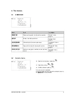
Страница 5: ...th their own serial numbers Always state the serial numbers for possible requests Please enter this numbers here immediately after delivery Part Serial number How to find the serial number E LINK cont...
Страница 6: ...danger to life danger of injury possible serious material damage Caution This symbol stands next to safety instructions malfunctions and impairments of correct operation possible material damage Note...
Страница 7: ...on twine tying unit are tightened properly Power supply of the electronics must only be switched on when the machine is to be operated After the end of work the control system must immediately be disc...
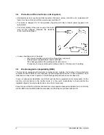
Страница 8: ...ccount if necessary remove sensitive parts cables sensors or the like prior to welding 3 5 Electromagnetic compatibility EMC The machine is equipped with electronic components and modules the function...
Страница 9: ...lected system data Systeminfo menu page 23 DIAGNOSIS DIAGNOSIS DIAGNOSIS DIAGNOSIS Diagnostic functions for checking the machine Diagnosis menu page 25 STATISTICS STATISTICS STATISTICS STATISTICS Mach...
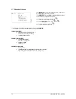
Страница 10: ...y Select MONITOR MONITOR MONITOR MONITOR menu keys or Confirm selection with key The following information are displayed in the menu MONITOR MONITOR MONITOR MONITOR Central main field Machine status b...
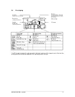
Страница 11: ...justment cutting device here 8 knives selected Automatic net tying automatic combined tying The PTO speed regulates the optional electric Lubrication pump and the measurement of the machine working ti...
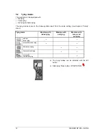
Страница 12: ...llowing table result from the setup setting see chapter 6 Setup menu Tying mode Machine with twine tying Machine with net tying Machine with twine and net tying manual twine tying automatic twine tyin...
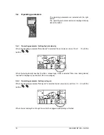
Страница 13: ...pter 5 3 1 Hydraulic switch Pick Up Bottom door see chapter 5 3 2 Hydraulic switch bottom door Cutting device see chapter 5 3 3 Hydraulic switch Cutting device RP 235 RP 235 S Pick Up bottom door Cutt...
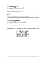
Страница 14: ...re not actuated in Pick Up position This setting has to be preferred to minimise the power consumption 5 3 2 Hydraulic switch bottom door Press centre button to select the bottom door The bottom door...
Страница 15: ...to 2 groups A 12 knife group and a 13 knife group It can be operated with one knife group or both knife groups at the same time The knife group being in cutting position is displayed here 12 knife gro...
Страница 16: ...ale density is selected the set value can be set from 1 10 with the buttons When the baling density reaches 10 while a manual tying mode is selected Stop max baling density reached is displayed see ch...
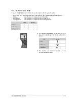
Страница 17: ...rpm revolutions per minute 5 6 Machine status Tying The running tying is displayed with two arrows that rotate around a bale 5 7 Machine status Opening the tail gate After tying has been finished the...
Страница 18: ...terial runs into the baler 5 9 Machine status Machine standstill Machine standstill after interrupted start of a twine or net tying is displayed by the standing material flow material flow no more ani...
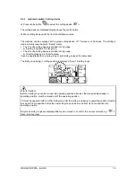
Страница 19: ...5 3 Hydraulic valve block Pick Up bottom door 8 knives optional 12 knives 9 knives optional 13 knives 17 knives optional 25 knives right button Select operating parameter see chapter 5 4 Operating pa...
Страница 20: ...Language Machine type Beep Open menu overview press key Select Setup menu keys or Confirm selection with key Select parameter keys and Change parameter keys and Either return to menu overview press ke...
Страница 21: ...ting device Delay Delay of the buzzer while twine tying or net insertion while net tying during the tying process see chapter 13 Appendix 0 5 0 sec in 0 5 sec steps Beep 0 50 in steps of 5 Net tying s...
Страница 22: ...y Operation left button Scroll display pages backwards centre button no function right button Scroll display pages forward no function Change parameter Change parameter Select parameter Select paramet...
Страница 23: ...FO O O O menu provides information about important system data Serial number Software version Software date The menu SYSTEMINFO SYSTEMINFO SYSTEMINFO SYSTEMINFO is exclusively for information Data can...
Страница 24: ...ions in the Systeminfo menu Key Operation left button no function centre button no function right button no function no function no function no function no function no function Open menu overview shor...
Страница 25: ...machine stopped Machine functions completely switched off In addition a fully automatic actor test is possible Extended diagnosis see chapter 8 2 Extended diagnosis Diagnostic functions while machine...
Страница 26: ...been stopped If the machine is started while the standard diagnosis is running no further diagnosis can be selected and with the next key stroke the control system returns to the MONITOR MONITOR MONIT...
Страница 27: ...E DIAGNOSIS DIGITAL SE DIAGNOSIS DIGITAL SE DIAGNOSIS DIGITAL SENSORS NSORS NSORS NSORS 1 2 the following sensors are displayed Diagnosis Digital Sensors 1 2 Abbreviation Name Sensor checks HOOK L HOO...
Страница 28: ...the status of all digital sensors and actors during the last 500 seconds Viewing of all signals in real time is also possible To the oscilloscope press centre button 8 1 2 Standard diagnosis Analog s...
Страница 29: ...f the display pages depends on the settings in the Setup menu see chapter 6 Setup menu Manual To toggle between DIAGNOSIS ACTORS MAN DIAGNOSIS ACTORS MAN DIAGNOSIS ACTORS MAN DIAGNOSIS ACTORS MANUAL U...
Страница 30: ...draulic block according to the version of the machine Automatic To toggle between DIAGNOSIS ACTORS MAN DIAGNOSIS ACTORS MAN DIAGNOSIS ACTORS MAN DIAGNOSIS ACTORS MANUAL UAL UAL UAL and DIAGNOSIS ACTOR...
Страница 31: ...ted actor channel will immediately stop machine operation and thus the extended diagnosis Indication for extended diagnosis the symbol AUTOMATIC flashes Attention danger of injury While the machine is...
Страница 32: ...ration left button Page backwards centre button Call up oscilloscope right button Page forwards Toggling between automatic and manual actor diagnosis Actor channel On Actor channel Off Select actor Se...
Страница 33: ...daily counter Bale number total Machine running time daily counter Machine running time total The total counters for bale number example 42 and machine running time example 44 1 h are cumulative count...
Страница 34: ...enu selection press key Or return to MONITOR MONITOR MONITOR MONITOR menu press key for 3 sec 9 1 Overview of the button functions in the Statistics menu Key Operation left button no function centre b...
Страница 35: ...ral errors occur at the same time the error message of the highest priority is displayed first A distinction is made between System error messages see from chapter 10 1 System error messages Standard...
Страница 36: ...pull plug DIN 9680B If the error occurs again after reconnection of the power supply baling can be processed with switched off electronics and by means of emergency tying see OI of the machine chapte...
Страница 37: ...g 2 Connect power supply Insert plug 1 into the socket at the tractor See OI of the machine chapter Emergency operation of the tying The red attachment plug for the twine tying is simply plugged into...
Страница 38: ...r The consumer is switched of automatically The error message can be acknowledged the output however remains blocked up to a new start of the system Acknowledge fault messages press key 10 7 Standard...
Страница 39: ...T KNIFE TRIGGERED Net knife was not triggered The error message can be acknowledged Subsequently remove cause Acknowledge fault messages press key 10 11 Standard error NET DOES NOT RUN NET DOES NOT RU...
Страница 40: ...5 Standard error 1 TAILGATE HOOK OPEN 1 TAILGATE HOOK OPEN 1 TAILGATE HOOK OPEN 1 TAILGATE HOOK OPEN A locking hook of the baling chamber is open The error message can be acknowledged or disappears au...
Страница 41: ...menu Monitor submenu page 42 SYSTEM SETUP SYSTEM SETUP SYSTEM SETUP SYSTEM SETUP Machine model toggling if several user interfaces are available System Setup submenu page 42 EEPROM EEPROM EEPROM EEPR...
Страница 42: ...ion with button 11 3 System Setup submenu The control can be used on other prepared machine families Select SYSTEM SETUP SYSTEM SETUP SYSTEM SETUP SYSTEM SETUP menu keys or Confirm selection with key...
Страница 43: ...ing keys or Page scrolling press key or Return to SYSTEM SERVICE SYSTEM SERVICE SYSTEM SERVICE SYSTEM SERVICE button 11 5 Self Test submenu A fully automatic self test can be carried out only in conne...
Страница 44: ...family Scroll up by one line Select machine family Scroll down by one line Select submenu Scroll down by one page 8 lines Select submenu Scroll up by one page 8 lines Open menu overview Call up select...
Страница 45: ...ors and actors see chapter 12 2 Oscilloscope for distance sensors The oscilloscope mode can be used to view and analyse the status of all sensors and actors during the last 500 seconds about 8 minutes...
Страница 46: ...ed data recording RUN recording is running Designation of the sensor actor channels see chapter 12 3 7 Page number Sensor actor status High damped connected Low uncovered disconnected Time window here...
Страница 47: ...urement value in the RUN mode this value is refreshed all the time here 2 30 V Zoom factor here factor 2 5 Offset zero point here 1 0 V Cursor Cursor position here 490 2 sec Actual measurement value i...
Страница 48: ...responding to a window size e g window size T 10 seconds window size T 20 seconds window size T 50 seconds window size T 100 seconds window size T 200 seconds window size T 500 seconds Position the se...
Страница 49: ...ctor by means of the keys and 12 3 6 Function Offset only for the oscilloscope for analog sensors The Offset function can be used to shift the origin of the displayed value range that means the vertic...
Страница 50: ...R Locking device right MESS MESS MESS MESS Net knife triggering MESS MESS MESS MESS Net knife TMOT TMOT TMOT TMOT Twine motor NETZ NETZ NETZ NETZ Net run B1 B1 B1 B1 Valve B1 PRES PRES PRES PRES Press...
Страница 51: ...lloscope for distance sensors Zoom factor 1x 2 5x 5x 10x only for oscilloscope for distance sensors Reduce selected oscilloscope parameters Page shown Time window set 10s 20s 50s 100s 200s 500s Cursor...
Страница 52: ...be set in menu setup see chapter 6 Setup menu and is 4 sec in this diagram TWINE TYING Buzzer Twine motor Delay 0 5 0 sec 8 0 sec 3 0 sec 3 0 sec Delay 0 5 0 sec 5 0 sec Delay 0 5 0 sec 8 0 sec 3 0 s...