Weldclass WeldForce WF-180MST Скачать руководство пользователя страница 7

7

1.  Fitting Wire Spool

1.1  Open wire feeder compartment door. Fit wire 

spool to spool holder post. Ensure that 

wire exits from the bottom of the spool. 
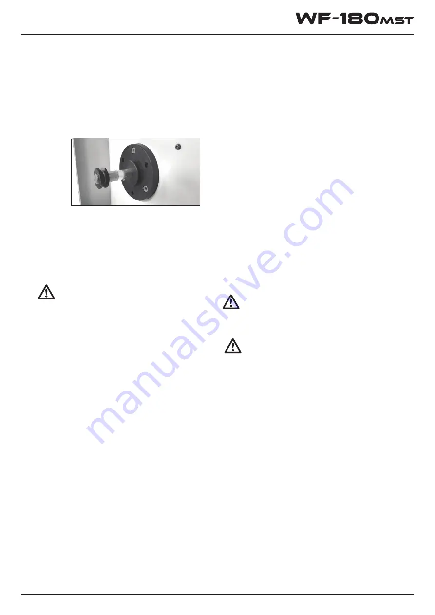
100mm/1kg Spool Set Up:


Use plastic slotted washed/spacer and 

threaded nut as shown here;


1.2  200mm/5kg spools only: Before replacing 

spool retaining nut, set spool brake tension 

by adjusting the smaller nut inside the spool 

hub. Spool should be able to rotate freely, 

but not continue to rotate when drive stops. 

Tension may need to be adjusted as spool 

weight decreases.


WARNING!

Excessive spool brake tension will cause wire 

feeding issues and affect welding performance 

as well as premature failure/ wear of wire feed 

components.

1.3  Feed the wire from the spool through the wire 


drive inlet guide (18) into the wire feeder.

2.  Loading Wire Feeder

2.1  Release the wire feed tension arm (20) by 


pivoting the wire feed tension adjustment 


lever (19) towards you from the vertical 


‘locked’ position.

2.2  Check the wire drive roller (22) groove 


matches the selected MIG wire type and 


size. The drive roller will have two different 


sized grooves; the size of the groove in use 


is stamped on the side of the drive roller. For 


flux cored ‘soft’ wire, such as that used in 


gasless MIG welding, the drive roller groove 


has a serrated profile (known as knurled). For 


solid core ‘hard’ MIG wire, the drive roller 


groove used has a ‘v’ shaped profile. If 


necessary, remove and change the drive roller 


by rotating anti clockwise and removing the 


drive roller retainer (21).

2.3  Once the correct drive roller (22) is selected 


and fitted and the drive roller retainer (21) is 


secured in place, manually feed the wire 


through the wire drive inlet guide (18), 


through the drive roller groove and into the 


outlet wire guide tube. Ensuring that the wire 


is correctly seated in the drive roller groove, 


replace the wire feed tension arm (20) and 


lock it into place by pivoting the wire feed 


tension adjustment lever (19) back to the 


vertical position.

3.  Adjusting Wire Feed Tension

This is accomplished by winding the knob on the 

tension adjustment lever (19). Clockwise will 

increase tension, anti-clockwise will decrease drive 

tension. Ideal tension is as little as possible, while 

maintaining a consistent wire feed with no drive 

roller slippage. Check all other causes of excess 

wire feeding friction causing slippage first, such as; 

incorrect/ worn drive roller, worn/ damaged torch 

consumables, blocked/ damaged torch wire guide 

liner, before increasing wire feed tension. There is a 

number scale on the tension adjustment lever (19) 

to indicate the adjustment position. The higher 

the number indicated, the higher the tension that 

is set.

WARNING!


Before changing the feed roller or wire spool, 


ensure that the mains power is switched off.

WARNING!


The use of excessive feed tension will cause  


rapid and premature wear of the drive roller, the


support bearing and the drive motor/gearbox.

3.4  Check that the correct matching MIG wire, 


drive roller (22) and MIG torch tip are fitted.

3.5  Connect the machine to suitable mains power 


using the mains input power lead (13). Switch 


the mains power switch (14) to ‘on’ to power 


up the machine. Set the welding mode switch 


(7) to ‘MIG’ position.

3.6  You are now ready to feed the wire through 


the torch. With the wire feeder cover open, 


pull the trigger of the MIG torch to check that 


the wire is feeding smoothly through the 


feeder and into the torch.

3.7  Set the wire feeding speed knob (5) to 


maximum. With the torch tip removed 


from the torch and the torch laid out as 


straight as possible, depress MIG torch trigger 


until the wire feeds out through the end of 


the MIG torch. Replace the tip on the MIG 


torch and trim off any excess wire.

MIG Welding Operation

Содержание WeldForce WF-180MST

Страница 1: ...OPERATING INSTRUCTIONS by To qualify for full 24 month warranty you must register within 30 days of purchase See inside for details IMPORTANT...

Страница 2: ...30 days of purchase Please register your warranty now by going to www weldclass com au weldforcewarranty You will need a A copy of your purchase invoice receipt b Your machine serial number which can...

Страница 3: ...r Supply Operating Environment Welding Settings Tips Tricks Accessories Spare Parts Care Maintenance MIG Basic Welding Guide MIG Welding Troubleshooting MMA Stick Basic Welding Guide MMA Stick Trouble...

Страница 4: ...y Cycle MIG 144A 60 ARC TIG 128A 60 MIG Wire Size 0 6 0 8 0 9mm MMA Electrode Size 1 6 3 2mm TIG Tungsten Size 1 6mm Spool Size 200mm 4 5kg or 5kg Input Power 240V 10A A Input Power MIG Output Power S...

Страница 5: ...mains power input lead 14 Mains power switch 15 Wire spool holder 16 Wire drive inlet guide 17 Wire feed tension adjustment 18 Wire feed tension arm 19 Wire drive roller retainer 20 Wire drive roller...

Страница 6: ...Lights when duty cycle is exceeded and thermal protection is activated When thermal protection is activated welding output will be disabled until machines cools sufficiently and overload indicator lam...

Страница 7: ...ng that the wire is correctly seated in the drive roller groove replace the wire feed tension arm 20 and lock it into place by pivoting the wire feed tension adjustment lever 19 back to the vertical p...

Страница 8: ...electrical connection to the welding torch 6 ARC MMA Welding Operation 6 1 Connect the earth cable quick connector to the negative welding power output socket 10 Connect the earth clamp to the work p...

Страница 9: ...will need to be rested for 8 minutes All duty cycle ratings are based on an ambient air temperature of 40 C with 50 humidity which is the international standard for such a rating In an environment wit...

Страница 10: ...go to www weldclass com au BZL25parts For machine parts go to www weldclass com au machines or contact your Weldclass distributor The compatible TIG torch for this machine is Weldclass 9 17 torch wit...

Страница 11: ...ry basic concepts in MIG welding where a welding gun is hand held and the electrode welding wire is fed into a weld puddle and the arc is shielded by a gas GMAW or flux cored wire FCAW Keep your Weldi...

Страница 12: ...by machine It is commonly used to weld large diameter electrodes in the flat and horizontal position and small electrode diameters in all positions The process is used to a lesser degree for welding s...

Страница 13: ...e Arc Voltage Welding current wire feed speed Travel speed Secondary Adjustable Variables These variables cause changes in primary adjustable variables which in turn cause the desired change in the be...

Страница 14: ...Speed resulting in a shorter arc Less Current Wire Speed will reduce the current and lengthen the arc Increasing the welding voltage hardly alters the current level but lengthens the arc By decreasing...

Страница 15: ...When there is a gas problem the result is usually porosity within the weld metal Porosity always stems from some contaminant within the molten weld pool which is in the process of escaping during soli...

Страница 16: ...by 16 Other weld problems can be reduced by checking the following points...

Страница 17: ...Electrodesaregenerallyconnectedtotheelectrode holder with the electrode holder connected positive polarity The work lead is connected to the negative polarity and is connected to the work piece If in...

Страница 18: ...ion of the weld metal and to produce sound joints In general surfaces being welded should be clean and free of rust scale dirt grease etc Slag should be removed from oxy cut surfaces Typical joint des...

Страница 19: ...on t be worrying then about being burnt or sparks setting alight to your clothes Place the work so that the direction of welding is across rather than to or from your body The electrode holder lead sh...

Страница 20: ...lded Joints Having attained some skill in the handling of an electrode you will be ready to go on to make up welded joints A Butt Welds Set up two plates with their edges parallel as shown in Figure 1...

Страница 21: ...eing sloped about 20 away from the perpendicular position to prevent slag from running ahead of the weld Refer to Figure 1 23 Do not attempt to build up much larger than 6 4mm width with a 3 2mm elect...

Страница 22: ...efore the metal freezes Examples of Vertical Fillet Welds Fig 1 27 Pause at edge of weave allows weld metal to build up and eliminates undercut Note Weld contour at edge of weave CORRECT INCORRECT Til...

Страница 23: ...23 MMA Stick Troubleshooting...

Страница 24: ...ectric Current Inert Gas Tungsten Electrode Deposit Melted Area Penetration Base Material Protective Gas Rod Torch TIG Welding Fig 15 TIG Electrode Selection and Preparation Electrode Polarity Connect...

Страница 25: ...reparation Wandering ARC Diameteroftheflatdeterminesamperagecapacity Fig 16 3 ARC Welder Point Grinding Wheel Radial Ground Pointing the Electrode The electrode should be pointed according to the weld...

Страница 26: ...by 26 TIG Welding Troubleshooting...

Страница 27: ...s practices not related to personal injury MIG Welding Operation 1 Maintain labels and nameplates on the welder These carry important information If unreadable or missing contact Weldclass for a repla...

Страница 28: ...strictly observe all safety rules and take precautionary actions welding products and welding processes can cause serious injury or death or damage to other equipment or property Safepracticeshavedev...

Страница 29: ...minating the hazard 6 After welding make a thorough examination for evidence of fire Be aware that visible smoke or flame may not be present for some time after the fire has started Do not weld or cut...

Страница 30: ...fitted with a proper shade of filter see AS 60974 1 AS NZS 1337 1 and AS NZS 1338 1 Safety Standards to protect your face and eyes when welding or watching 2 Wear approved safety glasses Side shields...

Страница 31: ...ecific application maintain them and their associated parts in good condition 6 Turn your face away from the valve outlet when opening the cylinder valve 3 If ventilation is poor use an approved air s...

Страница 32: ...by 32...

Страница 33: ...ely replacement of such parts 6 Warranty claims made where the owner operator of the machine is not willing or not able to provide any information required by Weldclass Welding Products to process the...

Страница 34: ...by 34...

Страница 35: ...35...

Страница 36: ...by www Weldclass com au WF 180MST...

Отзывы: