2.26
Dial Vacuum Gauge
A dial vacuum gauge is incorporated in the vacuum system. The dial gauge is located in the top front section
of the system. The dial vacuum gauge is commonly used to indicate vacuum level when operating in the
rough vacuum range (0 to 29.9”Hg) Dial vacuum gauges give negative pressure - that is pressure below
atmospheric. The reference point for the gauges is atmospheric pressure. Please keep in mind that atmo-
spheric pressure tends to vary from day to day. As a result of this variability, a dial vacuum gauge will
indicate slightly different maximum vacuum readings from day to day.
2.27
Vacuum Level Regulation
Vacuum level regulation is accomplished with an adjustable bleed valve. The adjustable bleed valve allows
close control of pressure in your apparatus. Pressure may be set between roughly atmospheric pressure and
the maximum vacuum obtainable (9 torr, 29.6 in Hg).
2.28
Vacuum Connections
All Dry Vacuum Pumps come with intake and discharge hose barbs which accept 3/8” ID rubber pressure/
vacuum hose. Hose clamps should be used to hold the hose in place. Since all six models operate in the
viscous flow range, the small diameter of the hose will generate minimal conductance loss. For best results,
Welch recommends the length of the tubing between the pump and the chamber be kept as small as possible.
2.29
Vacuum Gauges
Typical in the rough vacuum range, a dial vacuum gauge is used to measure pressure in mm, Hg or inches of
Hg. The dial vacuum gauge gives negative pressure – that is pressure below atmospheric. The reference
point for the vacuum gauge is atmospheric pressure.
Please keep in mind that atmospheric pressure tends to vary from day to day. As a result of variability, the
dial vacuum gauge will indicate slightly different maximum vacuum readings from day to day.
2.30
Traps
2.31
The need for a Trap
The pumps will handle humid air. All wetted aluminum parts are treated for corrosion protection from moisture.
All other wetted parts are stainless steel. If there is a chance liquid may be drawn from the process under
evacuation, Welch recommends a liquid trap be placed between the process and the pump. A simple liquid trap is
a filtering flask.
When a heavy load of water vapor is evolved from the vacuum process, a cold trap is recommended to help
prevent damage to the pump mechanism. The cold trap, immersed in a suitable Dewar flask, is installed so
that the water vapor may come in contact with the surfaces of the trap and condense. Commonly used
refrigerants are liquid nitrogen or dry ice and acetone or alcohol. Dry ice provides sufficient cooling to freeze
out most heavy water vapor loads. A variety of cold traps are available from Welch.
The symptom of a high water vapor load is if you have droplets coming out of the exhaust port. If you see
droplets of water, Welch recommends you use a cold trap to capture the water before entering the pump or
dilute the water vapor stream by adding dry nitrogen to the gas flow. Please call our customer service
department for additional information at (847) 676-8800 Ext. 1.
2.32
The care of a Trap
When using a cold trap the refrigerant should be maintained at a high level in the flask to keep the trap at a
uniformly low temperature. If the trap is re-warmed it may allow re-evaporation of the condensate. The
refrigerant add tube on the liquid nitrogen trap should not be obstructed as the refrigerant boil-off can produce
dangerously high pressures. If the trap becomes saturated it should be disconnected from the system, drained
and cleaned. An increase in pressure in the vacuum system will normally indicate that the trap has become
saturated. To clean the trap, remove the trap from the system and allow the trap to warm up and rinse off the
condensate with a suitable solvent in a fume hood. Thoroughly clean and dry the trap before reinstalling into
the system.
7
Содержание 2560
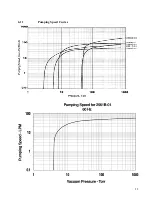
Страница 11: ...6 11 Pumping Speed Curves 11 ...
Страница 21: ...21 ...


