


- 35 -
9.2
Position Sensors
The gripping module has an integrated position measurement system with which the position of the base
jaws is measured relatively. The position value corresponds to the spacing of the two base jaws. The inner
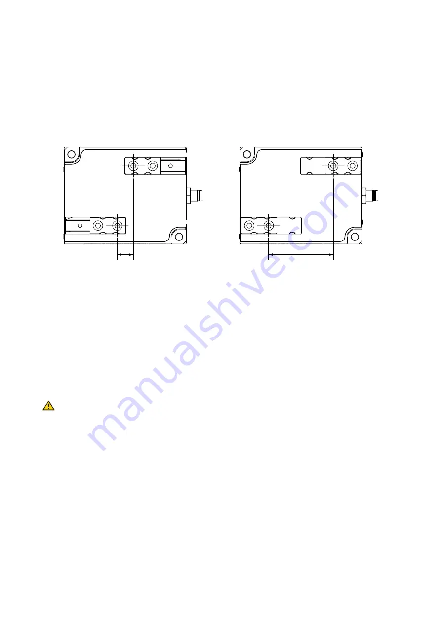
limit corresponds to the value 0 mm. Figure 11 shows the correlation between the position value and the
position of the base jaws using the example of the IEG 76-030. The current position value is transmitted in
the cyclic process data.
Figure 11:Example: position value IEG 76-030
9.3
Reference Run
Due to the relative position measurement system, the finger position is yet unknown when the gripping
module is activated. The module must be referenced before it can execute movement commands. For this
purpose, the module moves the base jaws with defined force and speed to the outer limit and uses this
position as a reference value.
Keep the traversing range of the fingers free during the reference run to avoid collisions and faulty
referencing.
If an individual application makes an outwards reference run impossible, e.g. if it would lead to a collision
with a part or with the environment, the direction of the reference run can be reversed and the inner limit
can be used (see chapter 8.2.3.1).
9.4
Virtual Position Switches
To detect different end positions, up to four virtual position switches can be parameterized. These position
switches are realized in the control software of the gripping module (
“
virtually
”
). Their switching status is
transmitted via the cyclic process data of the gripping module.
You can determine the center position and the width of the detection range for each position switch. The
position switches do not save their status but provide a momentary signal. To detect an end position relia-
POS=0
(Inner limit)
POS=3000
(Outer limit)