Weinzierl KNX ENO 634 Скачать руководство пользователя страница 3

KNX ENO 634 

WEINZIERL ENGINEERING GmbH 

EN 

2013-08-14 

Page 3/11 


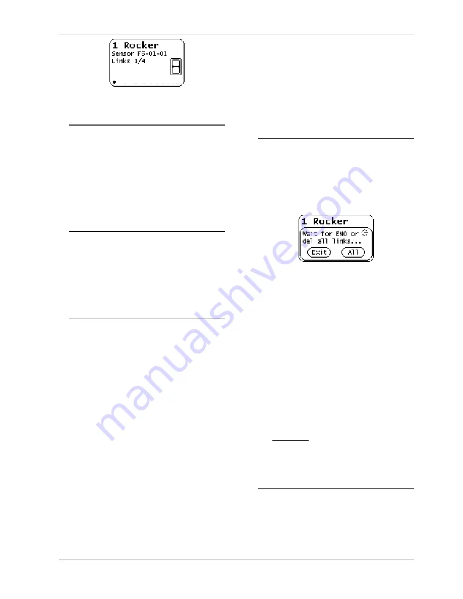
Fig. 4: Channel setting display 


Programming the individual address 


Programming  the  KNX  individual  address  with  ETS 
requires that the programming button T3 ("KNX Prog. 
mode")  be  pressed.  If  the  programming  or  learning 
mode is active, the red LED ("KNX Prog. mode LED") 
will be on. It turns off once the device has successfully 
received  the  individual  address.  Afterwards,  Group 
Addresses  and  Parameters  can  be  programmed  by 
the ETS. 
 

Linking to EnOcean-devices 


Before linking to EnOcean devices, the functions have 
to be programmed for each channel with the ETS. Per 
channel  typically  only  one  EnOcean  device  can  be 
linked.  For  switches,  window  handles  and  window 
contacts up to four links per channel are possible. 
For  actuator  channels  any  number  of  RF  actuators 
can be learnt. 

Linking mode for RF sensors 


The  operation  of  the  gateway  during  the  teach-in  of 
wireless sensors is done using the two buttons below 
the display. 
If  the  device  is  in  normal  mode,


the  push  button  T2 

activates,  by  short  key  presses,  the  channel  mode 
and  changes  to  the  next  channel.  The  display  shows 
the  current  channel  number  and  the  number  of  con-
nected  devices.  Also  the  ETS  configured  text  will  be 
shown for every channel (Fig. 4). 
With  a  long  press  of  T2  on  the  visible  channel,  the 
linking  mode  is  activated.  If  the  device  matches  the 
selected  function  via  the  parameter  configuration,  a 
transmitting  device  can  be  connected  to  the  current 
channel.  A  connection  is  created  by  pressing  the 
learn-button  of  the  sensor.


Window  handles  and 

switches must be operated for teach-in because they 
do not have a separate learn button. 
To avoid that other transmitting devices are stored by 
accidental  activation  during  the  programming  phase, 
devices can be programmed only after 3-times activa-
tion. For this purpose in the general parameters ‘Link 
switches/handles (RPS) after 3 tel.’ must be selected. 
The sensor has to send three telegrams within 10 se-
conds to be linked. 
The  link  mode  is  terminated  by  a  short  press  of  the 
left  key  T1,  as  well  as  automatically  after  5  minutes 

without operation. 
 
Quick guide linking mode for RF-sensors 

1.  T2 short press to select the desired channel. 
2.  T2  long  press  to  activate  the  learning  mode 

("Wait for ENO ..."). 

3.  Activate the learning mode in the RF-sensor. 
4.  The sensor is now programmed 


Deleting links for RF sensors 


Links with RF sensors can be deleted in several ways. 
With a long press on T1 the delete mode is activated 
for the current channel. The sensor can now be delet-
ed from the visible channel by pressing the learn but-
ton  on  the  RF  sensor.  It  is  also  possible  to  delete  all 
assignments  of  the  selected  channel  by  pressing  T2 
("All"). It is not required to operate the RF sensors. 


Fig. 5: Deleting links 

 
By programming the application program via the ETS 
all  programmed  sensors  of  all  channels  will  be  delet-
ed, when the "Delete all links after download" function 
in the general parameter is enabled. 
If  the  function  of  a  channel  has  been  changed,  pro-
gramming  the  parameters  with  the  ETS  deletes  the 
links of the modified channel.


The  link  mode  is  terminated  by  a  short  press  of  the 
left  key  T1,  as  well  as  automatically  after  5  minutes 
without operation. 
 
Quick guide linking mode for RF-sensors 

1. 

T2 short press to select the desired channel

.


2. 

T1 long press to activate the delete mode ("Wait 
for ENO or del all left ..."
). 

3. 

Activate  the  learning  mode  at  the  desired  radio 
sensor to delete these. 
Alternatively: 
T2 long press to delete all taught-in wireless sen-
sors from the selected channel. 


Linking mode for RF-actuators 


The operation of the gateway during the linking of ac-
tuators is similar to the linking of sensors. First the ac-
tuator is placed in linking mode. A long press of T2 at 
the  visible  channel  activates  the  linking  mode  in  the 
gateway. The display shows the “select key” selection 

(Fig.  6).  The  action  point  (top  or  bottom)  of  the  learn 
telegram can be selected with the T2 button. On some 

Содержание KNX ENO 634

Страница 1: ... gateway supports logical and control functions and in cludes radio repeater functionality The KNX ENO 634 is divided in 32 channels Each channel can be as signed to one of the following functions Link from EnOcean sensor to KNX Switch functions Switching Dimming Shutter Scene Window handles Window contacts Access card switches Press switches Temperature sensors Humidity sensors Light sensors Pres...

Страница 2: ...er Deleting links for RF sensors and Deleting links for RF actua tors Key press T1 short Exit Leave channel linking mode Key press T2 long Add Start linking mode Refer to chapter Linking mode for sensors and Linking mode for actuators Key press T2 short Active Activate or change the channels 1 32 Key press T3 Activate KNX Prog mode The KNX device can now receive a new individual ad dress Refer to ...

Страница 3: ...handles RPS after 3 tel must be selected The sensor has to send three telegrams within 10 se conds to be linked The link mode is terminated by a short press of the left key T1 as well as automatically after 5 minutes without operation Quick guide linking mode for RF sensors 1 T2 short press to select the desired channel 2 T2 long press to activate the learning mode Wait for ENO 3 Activate the lear...

Страница 4: ...n telegram will be compared to see if it has been assigned to a Channel If so the channel is shown shortly in a matrix on the LCD display De pending on the configured function there will be one or more telegrams sent on the bus The gateway only sends telegrams to the KNX bus when a correspond ing EnOcean telegram has been received If an EnOcean telegram is not assigned to any channel only the sign...

Страница 5: ...ush if the actu ator supports this Comm Object Type KNX Size Channel Scene 18 001 1 Biyte Other switches and contacts Fig 8 Other switches and contacts In the submenu Other switches and contacts window contacts window handles key card switches and pressure switches can be integrated For window handle sensors three states can be de tected Window is open tilted or closed When turn ing the handle in ...

Страница 6: ...is available as a 2 byte float value Comm Object Type KNX Size Channel Lux 9 004 2 Byte Presence sensors Fig 12 Occupancy sensors In this section presence sensors and motion detectors can be integrated Comm Object Type KNX Size Channel presence 1 018 1 Bit Light Temperature und occupancy sen sors Fig 13 Light Temperature und occupancy sensors Light intensity and temperature are each mapped to a co...

Страница 7: ...076 4 Byte Channel Current water l h 9 025 2 Byte Environmental and weather sensors Fig 17 Environmental sensors The following environmental sensor types can be pro grammed Weather station sunlight northern hemi sphere date time and day direction and geographic position Depending on the setting there are different communication objects for each sensor type Weather station Comm Object Type KNX Size...

Страница 8: ...le contact input On or off will be sent Comm Object Type KNX Size Channel Window open 1 019 1 Byte HVAC Actuator for valve drive Fig 21 HVAC actuator In this configuration battery operated heating and air actuators can be controlled The temperature values sent by the actuator will be sent to the bus A tele gram is sent when the EnOcean device signals a low battery Battery operated heating and vent...

Страница 9: ...automatic control A typical application for the fully automatic control is the lighting of a corridor The light is turned on in presence when the current brightness value is below the threshold By manual operation the light can be switched on or off for a specific time Semi automatic control The semiautomatic mode allows the user or residents to turn the lights on and off manually The semi automat...

Страница 10: ...r level corresponding to the config ured condition Is this condition is fulfilled the value 1 will be sent via the output datapoint Comm Object Type KNX Size Channel Trigger value in A D 5 000 1 Byte Channel Trigger binary out A D 1 001 1 Bit Trigger float Up to 2 float triggers can be implemented on one channel The trigger compares the input value with the configured trigger level corresponding t...

Страница 11: ...d data is displayed also in hexadecimal cod ing in the second numeric part If a message is sent by the gateway it is displayed in the first position of the line with an S The ID used by the gateway and the transferred data are also shown Fig 27 EnOcean bus monitor KNX bus monitor The KNX bus monitor displays the messages at the object level Therefore only group telegrams are visi ble which address...

Отзывы: