


Part number 550-141-608/0908
3
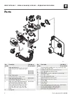
GOLD GV Series 1 – 4 Blower Assembly or Burner — Replacement Instructions
Replacement instructions
Shut off main gas valve and disconnect electricity to boiler. Failure to do so can cause severe
injury, death or substantial property damage
Wait until igniter is cooled down before proceeding. Failure to do so can cause severe injury.
Do not disassemble blower housing. A fire or explosion causing severe personal injury, death
or substantial property damage could result.
To remove blower assembly or
burner
1. Remove jacket top and front panels.
2. Remove control tray shipping screw and lift up
control tray, setting it out of your way (Series 1 and
2). Remove gas supply piping.
3. Disconnect (refer to items identified on page 2):
a. gas tubing from gas valve (left-hand thread
- Series 1-3) (4 screws - Series 4), item 9
b. pressure switch hoses, item 3
c. hose from gas valve to gas/air manifold,
item 7
d. inlet air hose, item 16
e. blower motor wiring harness from control
module
f.
igniter harness from igniter plug
g. blower support bracket
h. gas supply manifold with bracket from blower
housing
i.
ground wire from blower housing
j.
gas/air manifold and orifice plate, items 6
and 7.
4. Remove 2 ignitor screws and lockwashers. Carefully
remove igniter, item 12.
Use care when removing and
handling igniter. Igniter is very
brittle and can break if not handled
carefully.
Do not touch!
5. Remove nuts and washers from studs at blower
housing mounting bracket and casting.
6. Grasp blower assembly and pull free from studs.
Turn clockwise until blower assembly can be
removed safely from inside of boiler.
7. Pull out burner cone and ring assembly and old
gasket, items 1 and 2, to inspect for dust or soot
accumulation. Clean or replace as necessary.
To install blower assembly or
burner
1. Place new blower housing gasket over studs at
combustion chamber opening.
2. Re-install burner cone and ring assembly into
combustion chamber.
3. Position blower assembly over studs. Install nuts
and washers and tighten until blower housing
gasket starts to compress.
4. Install igniter and new igniter gasket. Fasten with
screws and washers. Tighten until lockwasher starts
to compress.
Igniter body will crack if screws are
over-tightened.
5. Replace control tray.
6. Connect:
a. Gas/air manifold and orifice plate (tighten
screws until metal-to-metal contact is made
around entire manifold)
b. Gas tubing from gas valve (left-hand thread
- Series 1-3) (4 screws - Series 4)
c. Pressure switch hoses
d. Hose from gas valve to gas/air manifold
e. Inlet air hose (tighten hose clamp)
f.
Blower motor wiring harness to control
module
g. Igniter harness to igniter plug
h. Blower support bracket
i.
Gas supply manifold with bracket to blower
housing
j.
Ground wire to blower housing.
k. Gas supply piping
7. Be sure all wiring and hose connections are secure
and in their proper locations.
8. Turn on electrical power and gas. Check boiler
normal sequence of operation and follow check-out
procedure in Boiler Manual.
9. Replace jacket front and top panels.


