
D
DEUTSCH
HILfSSpaNNUNG
Nennspannung: 230 V
AC
±20% / 50 Hz
Max periodische Spannung: 300 V
AC
Max nichtperiodische Spannung: 320 V
AC
(20 ms)
Verbrauch: max 5 VA
Vorsicherung: Typ T, 100 mA (extern zu installieren)
ETHERNET KOMMUNIKaTION
Protokoll: HTTP, FTP, TCP, IP, MODBUS TCP
MODBUS TCP Schnittstelle: 502
Netzwerkschnittstelle: 10/100 Base-T
Kommunikationsgeschwindigkeit: 10/100 Mbps
Stecker: RJ-45
SERIELLER BUS
Typ: Infrarot-Schnittstelle
Kommunikationsgeschwindigkeit: 38400 bps
SpEICHER
Datenspeicher: eingebauter – nicht flüchtiger Speicher
KONfORMITÄTSERKLÄRUNG
EN61000-6-2 Störfestigkeit (Industriebereich):
EN61000-4-2 Elektromagnetische Verträglichkeit, EN61000-4-3 Abgestrahlte RF Störung,
EN61000-4-4 schnelle Transienten (Burst), EN61000-4-5 Stoßspannungen (Surge),
EN61000-4-6 leitungsgeführte RF-Signale, EN61000-4-11 Spannungseinbrüche am AC Hilfspannung
EN55011 Klasse A: Strahlungs- und Leitungsemissionen
Sicherheitsbestimmungen: EN60950
aNSCHLIESSBaRER LEITER
Klemmen: 0,14...2,5 mm
2
UMWELTBEDINGUNGEN
Arbeitstemperaturbereich: zwischen -15°C und +60°C
Lagertemperaturbereich: zwischen -25°C und +75°C
Relative Luftfeuchte: 80% max ohne Kondensation
Schutzgrad: IP20
GB
ENGLISH
pOWER SUppLY
Rated voltage: 230 V
AC
±20% / 50 Hz
Max repetitive voltage: 300 V
AC
Max non repetitive voltage peak: 320 V
AC
(20 ms)
Consumption: max 5 VA
Fuse: T type, 100 mA (to be mounted externally)
ETHERNET COMMUNICaTION
Protocol: HTTP, FTP, TCP, IP, MODBUS TCP
MODBUS TCP port: 502
Network interface: 10/100 Base-T
Communication speed: 10/100 Mbps
Connector: RJ-45
SERIaL COMMUNICaTION
Type: optical port
Communication speed: 38400 bps
RECORDINGS
Data memory: internal, non-volatile
STaNDaRDS COMpLIaNCE
EN61000-6-2 Immunity for industrial environments:
EN61000-4-2 Electrostatic discharge, EN61000-4-3 RF radiated disturbance,
EN61000-4-4 Fast Transient (BURST), EN61000-4-5 Overvoltage (Surge),
EN61000-4-6 RF conducted disturbance, EN61000-4-11 Voltage dips and short interruptions,
EN55011 Class A: radiated emissions, conducted emissions
Safety: EN60950
WIRE DIaMETER fOR CONNECTION TERMINaLS
Diameter: 0.14...2.5 mm
2
ENvIRONMENTaL CONDITIONS
Operating temperature: between -25°C and +55°C
Storage temperature: between -25°C and +75°C
Humidity: 80% max without condensation
Protection degree: IP20
TECHNISCHE EIGENSHAFTEN
TECHNICAl FEATURES
lED FUNKTIoNEN
lEDS FUNCTIoNAlITY
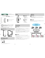
Zur Anzeige des Zustandes und der Linkaktivität befinden sich LEDs auf der Frontseite des Moduls.
LEDs are available on the module front panel to provide link activity and general status.
D
DEUTSCH
lED FARBE
MElDUNG
BEDEUTUNG
lED DES STANDES
GRÜN
Dauerleuchten
Laufender Neustart des Moduls (60...90 s)
GRÜN
Blinkend
(50ms ON, 2s Periode)
Kommunikation zum Zähler=OK
ROT
Blinkend
(500ms ON, 1s Periode)
Kommunikation zum Zähler=Fehler/fehlend
lED ÜBER lINKAKTIVITäT
-
Aus
Netzkabel getrennt
GRÜN
Dauerleuchten
Link OK
GRÜN
Blinkend
Link activ
GB
ENGLISH
lED ColoUR SIGNAllING
MEANING
STATUS lED
GREEN
Always ON
Module firmware boot in progress (60...90 s)
GREEN
Blinking (50ms ON, 2s period)
Counter communication=OK
RED
Blinking (500ms ON, 1s period) Counter communication=fault/missing
lINK ACTIVITY lED
-
OFF
Network cable disconnected
GREEN
Always ON
Link OK
GREEN
Blinking
Link activity
FUNKTIoN WERKSEINSTEllUNG
SET DEFAUlT FUNCTIoN
D
DEUTSCH
Die Funktion WERKSEINSTELLUNG dient zum Rücksetzen aller Einstellungen auf die ursprünglichen
Werte (z.B. wenn die IP Adresse vergessen wurde). Um die Werkseinstellung wiederherzustellen
gehen sie wie folgt vor:
Das Modul ausschalten.
1.
Die Taste WERKSEINSTELLUNG drücken und gleichzeitig das Modul einschalten. Die Status
2.
LED blinkt dann rot.
Nach vorgenommener Werkseinstellung wird die LED dauerhaft rot leuchten und sie können
3.
die Taste wieder loslassen.
Während des Neustarts des Moduls (Zeit zum Neustart 60 bis 90s) wird die Statusled dann
4.
dauerhaft grün leuchten.
GB
ENGLISH
SET DEFAULT function allows to restore on the module default settings (e.g. in case of IP address
forgotten). To restore default settings, follow the instructions below:
Switch off the module.
1.
Keep pressed SET DEFAULT key and simultaneously switch on the module: status LED will
2.
blink red during the SET DEFAULT procedure.
At the end of SET DEFAULT procedure, status LED will be red continuously indicating to
3.
release the key.
During the module restart, the status LED will be green (time for module restart: 60...90 s).
4.
EINSTEllUNGEN /
SETTINGS
WERKSEINSTEllUNGEN /
DEFAUlT VAlUES
IP Adresse /
IP address
192.168.1.253
Subnet Mask /
Subnet mask
255.255.255.0
NTP Server /
NTP time server
ntp.nasa.gov
UTC Zeitkorrektur /
UTC time correction
+1
Benutzername und Passwort Administrator /
Administrator username & password
admin
Benutzername und Passwort Benutzer /
User username & password
user
ZäHlERVERWAlTUNG DURCH DEN WEB SERVER
CoUNTER MANAGEMENT VIA WEB SERVER
D
DEUTSCH
Der Zugang zur WEB-Seite des LAN GATEWAY kann mit jedem PC mit LAN oder Internetzugang
erfolgen, wenn der Grundanschluss richtig durchgeführt worden ist.
Die Web-Seiten des LAN GATEWAY Moduls sind auf 2 Benutzergruppen zugeschnitten:
Administrator
•
: vollständiger Zugang zu der Funktionen des Web Servers. Es dient zur
Zählerverwaltung, Einstellungen und Update des LAN GATEWAY und Accountmanagement.
Benutzer
•
: Beschränkter Zugang zur Web Server Funktionen (max. 20 Benutzerprofil einstellbar).
Verfügbare Funktionen
Administrator
Benutzer
Echtzeitwerte
Übertragung der gespeicherten Messwerte
Freigabe oder Sperren der gespeicherten Messwerte
Anzeige der Zählerangaben
Änderung der LAN GATEWAY Einstellungen
Update des Moduls LAN GATEWAY
Verwaltung der Zugangsprofile zum LAN GATEWAY
(Administrator und Benutzer)
Starten, Sperren, Rücksetzten der Teilzähler
Wenn Sie sichergestellt haben, das alle bis jetzt beschriebenen Anschlüsse richtig durchgeführt
worden sind, ist der Zugang zum Modul möglich. Schalten Sie den PC ein und gehen Sie wie folgt vor:
Starten Sie den Internetbrowser (z.B.: Internet Explorer, Mozilla Firefox) und schreiben Sie die IP
1.
Adresse des LAN GATEWAY Moduls in das Adressenfeld.
Schreiben Sie den Benutzernamen und das Passwort in die entsprechenden Eingabefelder.
2.
Bestätigen Sie Ihre Einträge mit der LOGIN Taste. Danach wird die LAN GATEWAY
3.
Inhaltsverzeichnis dargestellt.
GB
ENGLISH
LAN GATEWAY module web pages can be accessed by any PC connected to LAN or to Internet, if proper
connections have been carried out.
LAN GATEWAY web pages have been designed for two user type:
Administrator
•
: full web server use. It can manage the combined counter, carry out LAN GATEWAY
module setup, upgrade and manage its access accounts.
User
•
: limited web server use (possibility to add up to 20 User accounts).
Available functions
Administrator
User
Display measurements
Download measured data recordings
Enable or delete measured data recordings
Display counter status information
Change LAN GATEWAY module settings
Upgrade LAN GATEWAY module
Manage LAN GATEWAY module access accounts
(Administrator, User)
Start/stop/reset partial counters
To access LAN GATEWAY web pages, check that previously described connections have been carried
out, then turn on a PC and follow the instructions:
Run the Internet browser (e.g.: Internet Explorer, Mozilla Firefox) and type the LAN GATEWAY IP
1.
address in the web address field.
Type in the relevant fields proper Username and Password.
2.
Confirm with Login key and the LAN GATEWAY Home page will be displayed.
3.


