de
en
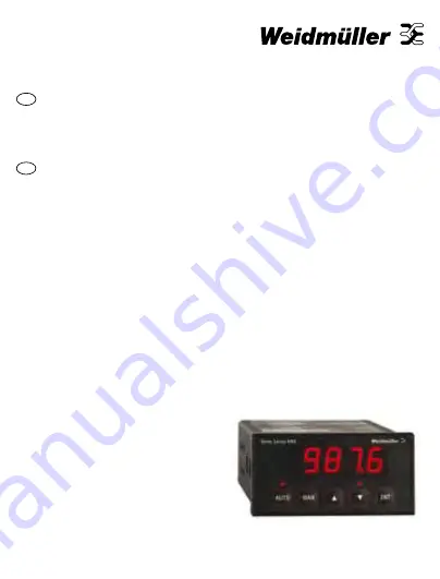
AMS400A
61001072/00/04.08
Bedienungsanleitung
Universelles Schnittstellengerät
3
Operatinginstructions
Universal interface device
24
Страница 1: ...de en AMS400A 61001072 00 04 08 Bedienungsanleitung Universelles Schnittstellenger t 3 Operating instructions Universal interface device 24...
Страница 2: ......
Страница 3: ...onfiguration 10 Konfiguration Analog zu Analog AA 12 Konfiguration Digital zu Analog dA 15 Konfiguration Digital zu Digital dd 17 Auswahl Kalibrierung des Analogeingangstyps 19 Auswahl und Kalibrierun...
Страница 4: ...stellen Sie das Steuerglied ber das Tastenfeld ein Status LEDs Die oberhalb jeder Taste befindliche Leuchtdiodenanzeige gibt den Status des AMS400A an Die LED AUTO zeigt an dass sich das Ger t im Auto...
Страница 5: ...rschiedenen Konfigurationstypen finden Sie weiter unten Ger teanzeige Das AMS400A zeigt je nach Konfiguration R ckmeldeinformationen des Prozesses oder das Steuerungssignal an Einschaltmodus Je nach K...
Страница 6: ...sklemmen durchgef hrt werden Dabei sind die in dieser Dokumentation enthaltenen Informationen landesspezifischen Bestimmungen und Sicherheitsvorschriften zu beachten AMS400A 5 7 6 Strom versorgung Spa...
Страница 7: ...ei 24 V DC Installationskonfigurationen Das vollst ndig konfigurierte AMS400A stellt drei Installationsarten zur Verf gung AA zwischen analoger Steuerungsvorrichtung und analogem Steuerglied dA zwisch...
Страница 8: ...lektromagnetischer St reinstrahlung m ssen alle Signalleitungen geschirmt sein oder in leitf higen Kabelkan len bzw in Rohren gef hrt werden Verwenden Sie eine f r Temperaturen von ber 70 C zugelassen...
Страница 9: ...gnal 5 0V Statusausg nge 6 AUTO MAN 7 bergabestatus 8 Masse Digitaleingang 9 Inkrementieren 10 Dekrementieren 11 Signal Analogeingang 12 Signal 13 ffner Inkrementieren Relaisausgang 14 Wurzelkontakt 1...
Страница 10: ...10 Sekunden Next S W Version v3 01 Softwareversion 3 01 Next Konfiguration der Anzeige Display Range dP Position des Dezimalpunkts Shift Next Accept dLO 0 0 Untergrenze des Anzeigebereichs z B 0 0 De...
Страница 11: ...Toggle Accept Calibrate Output COPn COPy Ausgangskalibrierung berspringen Ausg nge kalibrieren Toggle Accept Password PASS Passwort ndern Change Skip Save values SAVE Die nderungen werden in der Konf...
Страница 12: ...schen Steuerungsmodus zu gew hrleisten geht das AMS400A in einen speziellen bergabemodus Das Ger t bleibt im bergabemodus bis sich sein Ausgangspegel und der Ausgangspegel der Steuerung auf einem ann...
Страница 13: ...s spezifische Einstellungen Einstellung Anzeige Beschreibung ENT Manual Ramp Rate rr1 10 0 Angabe der manuellen Rampenrate Rate bei der der Ausgang manuell angepasst werden kann Dec Inc Next Accept Ha...
Страница 14: ...Steuer glied Steuerung P N 4 3 Man Kom Auto AMS400A 9 8 10 Wechseln des Betriebsmodis Man bewirkt einen Wechsel vom Automatikmodus in den manuellen Modus Auto bewirkt einen Wechsel vom manuellen Modus...
Страница 15: ...e zu sehen Durch Dr cken der Taste AUTO oder MAN k nnen Sie au erdem den Ausgangssignalpegel in Prozent anzeigen Statusausg nge ber einen digitalen Statusausgang zum Steuerungsger t wird der Betriebsm...
Страница 16: ...16 Anschlussschema f r Modus dA 1 2 R ckmeldung Signalquelle 12 11 AMS400A Steuer glied Steuerung P N 4 3 Ink Kom Dek AMS400A 9 8 10 Steuersignale Strom Spannungssignal Strom Spannungssignal...
Страница 17: ...rt der Bediener das Steuerglied von Hand und die automatischen Impulse werden ignoriert Anzeige Die Anzeige stellt ber den analogen Strom Spannungseingang R ckmeldeinformationen bereit Im Falle der An...
Страница 18: ...1 2 R ckmeldung Signalquelle 12 11 AMS400A Steuer glied Steuerung P N 13 18 Ink Kom Dek AMS400A 9 8 10 Steuersignale Strom Spannungssignal Ink Dek Signale f r Relaiskontakt Anschlussschema f r Modus...
Страница 19: ...den Dies erfordert eine Neukalibrierung des Ger ts Einstellbarer Eingangsbereich R1 R2 R3 R4 0 8 mA bis 0 24 mA 36R 68K Leer lassen 120K 0 4 V DC bis 0 12 V DC Leer lassen 1M 75K 120K 0 1 V DC Leer la...
Страница 20: ...erforderlichen Bereichs Warten Sie ein paar Sekunden bis sich das Signal stabilisiert hat und dr cken Sie dann ENT InHI Die Anzeige blinkt nicht mehr f r die Dauer von ca 10 Sekunden um anzuzeigen das...
Страница 21: ...ge setzen Sie die Jumper auf J1 und J2 F r Stromausg nge setzen Sie die Jumper nur auf einen der Pfostenstecker Kalibrierung des analogen Ausgangs Anforderungen an die Betriebsmittel Ein pr zises Digi...
Страница 22: ...ellt ist dr cken Sie ENT Save Fahren Sie mit der Konfigurationssequenz fort Hinweis Trennen Sie das Ger t nicht von der Netzspannung solange die Speichernachricht angezeigt wird Auswahl des Digitalein...
Страница 23: ...mm TAFELST RKE Max 18 0 mm 48 8 mm 44 4 mm 96 6 mm 60 0 mm 143 5 mm 15 5 mm 15 5 mm MAN AUTO ENT 2700 18 0 mm DICHTUNG 92 0 mm 0 8 0 0 mm AUSSCHNITT 45 0 mm 0 6 0 0 mm Montageschrauben nicht zu fest a...
Страница 24: ...trument Setup 30 Analogue to Analogue AA configuration 32 Digital to Analogue dA configuration 35 Digital to Digital dd configuration 37 Analogue Input type Selection Calibration 39 Output type Select...
Страница 25: ...D indicators above each key show the AMS400A s status AUTO LED shows that the unit is in Automatic mode MAN LED shows that the unit is in Manual mode AUTO LED flashing and MAN LED on indicates handove...
Страница 26: ...rom the controller according to the setup Power up mode You can setup the AMS400A for either Manual or Automatic control after power is restored to the unit Set up Review To review the setup simply sk...
Страница 27: ...d all relevant national electrical wiring and safety rules must be followed Locate the instrument in an area that is free from dust moisture and corrosive gases Do not cover the ventilation holes at t...
Страница 28: ...equipment and analogue control element dA between digital controlling equipment and analogue control element dd between digital controlling equipment and digital control element Analogue means standar...
Страница 29: ...ires to 7 mm from the ends Use a suitable ferrule for multistranded wires do not solder Terminal Signal 1 Neutral Power supply 2 Live 3 Signal Analogue output 4 Signal 5 0V Status Outputs 6 AUTO MAN 7...
Страница 30: ...W Version 3 01 Next Display set up Display range dP Decimal point position Shift Next Accept dLO 0 0 Display range lower limit e g 0 0 Dec Inc Next Accept dHI 100 0 Display range Upper limit e g 100 0...
Страница 31: ...y Skip input calibration Calibrate inputs Toggle Accept Calibrate Output COPn COPy Skip output calibration Calibrate outputs Toggle Accept Password PASS Change Password Change Skip Save values SAVE In...
Страница 32: ...after a period of manual control the AMS400A enters a special handover mode It remains in handover mode until its output level and the controller s are sufficiently close There are two ways to handov...
Страница 33: ...Description ENT Manual Ramp Rate rr1 10 0 Introduces the manual ramp rate Rate at which output can be manually adjusted Dec Inc Next Accept Handover Mode rAnP HErr Ramp mode handover method Error Mod...
Страница 34: ...rol Element Controlling Device L N 4 3 Man Com Auto AMS400A 9 8 10 Mode forcing signals Man causes switch from auto to manual mode Auto causes switch from manual to automatic mode Current Voltage Sign...
Страница 35: ...ant to display the flow rate You can also display the output signal level in percent by pressing the AUTO or MAN key Status Outputs There is a digital status output to the controlling device to signal...
Страница 36: ...36 1 2 Feedback signal source 12 11 AMS400A Control Element Controlling Device L N 4 3 Inc Com Dec AMS400A 9 8 10 Control Signals Current Voltage Signal Current Voltage Signal dA Mode Connection...
Страница 37: ...ator adjusts the element and the automatic signals are ignored Display The display provides feedback using the analogue current voltage input from the control element or from a suitable measuring devi...
Страница 38: ...1 2 Feedback signal source 12 11 AMS400A Control Element Controlling Device L N 13 18 Inc Com Dec AMS400A 9 8 10 Control Signals Current Voltage Signal Relay Contact Inc Dec Signals dd Mode Connectio...
Страница 39: ...below The Instrument will need recalibration Input Adjustment Range R1 R2 R3 R4 0 8 mA thru 0 24 mA 36R 68K Omit 120K 0 4 V DC thru 0 12 V DC Omit 1M 75K 120K 0 1 V DC Omit 68K Omit 82K Analogue Input...
Страница 40: ...I Set the signal source to the Highest value in the required range Wait a few seconds for the signal to stabilise and press ENT InHI Display will stop flashing for about 10 s to show that the instrume...
Страница 41: ...center of the main PCB and at right angles to it For Voltage outputs connect the jumpers across J1 and J2 For current outputs fit the jumpers to one post only Analogue Output Calibration Equipment re...
Страница 42: ...sing the or keys until the output is at the output range maximum When you are happy that the output is correct press ENT Save Continue with the setup sequence Note Do not remove the power while the sa...
Страница 43: ...PANEL THICKNESS Max 18 0 mm 48 8 mm 44 4 mm 96 6 mm 60 0 mm 143 5 mm 15 5 mm 15 5 mm MAN AUTO ENT 2700 18 0 mm GASKET 92 0 mm 0 8 0 0 mm CUTOUT 45 0 mm 0 6 0 0 mm Do not overtighten the mounting screw...
Страница 44: ...Weidm ller Interface GmbH Co KG Postfach 3030 32720 Detmold Klingenbergstra e 16 32758 Detmold Tel 49 5231 14 0 Fax 49 5231 14 20 83 info weidmueller com www weidmueller com 61001072 00 04 08...