


English
ACCESSORIES
7.2 BACKPLANE REPLACEMENT
The control accessories are mounted in the
backplane
slots. The slots are interchangeable, and any accessory
can be mounted in any slot in any quantity (except for communication network accessories, which are limited to one
per drive). By default, the CFW900 is supplied with the
backplane
CFW900-4SLOTS, which allows the installation
of up to 4 accessories (slots A to D). It is possible to replace the CFW900-4SLOTS with the CFW900-7SLOTS,
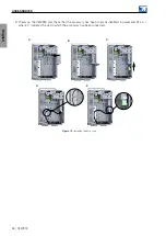
which expands the connection up to 7 accessories, following the steps in
(a)
Press the latch that holds the CFW900-4SLOTS
(b)
Pull the CFW900-4SLOTS as indicated and remove
it from the product
(c)
Position the CFW900-7SLOTS as shown in the
figure and push it in the indicated direction
(d)
Make sure that the CFW900-7SLOTS locked in
place
Figure 7.1:
Replacing the CFW900-4SLOTS with the CFW900-7SLOTS
7.3 INSTALLING THE CONTROL ACCESSORY
The control accessories are easy and quickly installed on the inverters using the plug-and-play concept. They may
be ordered separately and will be shipped in individual packages containing the components and the manuals with
detailed instructions for the product operation and programming. When an accessory is connected to the inverter,
the control circuitry identifies the model and informs the code of the connected accessory. They should only be
installed or changed with the inverter turned off, following the steps presented below and exemplified in
1. Remove the HMI from the inverter front.
2. Remove the two screws and detach the front cover.
3. Insert the accessory into one of the available slots on the backplane. (A)
4. Fasten the grounding screw. (B)
5. Make the connections to the plug-in connector and plug it into the accessory. (C)
6. Connect the cable shield to the grounding plate using metal clamps. (D)
7. Attach the identification labels (supplied with the backplane) to the accessory and to the plug-in connector.
(E)
8. Put the front cover and HMI back in place.
CFW900 | 93


