


V/f Scalar Control
CFW500 | 9-3
9
9.1 PARAMETERIZATION OF THE V/f SCALAR CONTROL
The scalar control is the inverter factory default control mode for its popularity and because it meets most
applications of the market. However, parameter P0202 allows the selection of other options for the control mode,
as per
Chapter 8 AVAILABLE MOTOR CONTROL TYPES on page 8-1
.
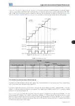
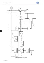
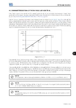
The V/f curve is completely adjustable in five different points as shown in
, although the
factory default defines a preset curve for motors 50 Hz or 60 Hz, as per options of P0204. In this format, point P
0
defines the amplitude applied at 0 Hz, while P
3
defines the rated amplitude and frequency and beginning of field
weakening. Intermediate points P
1
and P
2
allow the setting of the curve for a non-linear relationship between torque
and speed, for instance, in fans where the load torque is quadratic in relation to the speed. The field weakening
region is determined between P
3
and P
4
, where the amplitude is maintained in 100 %.
P0134
P0145
P0146
P0147
P
0
P
1
P
2
P
3
P
4
P0142
P0143
P0144
P0136
Output
frequency (Hz)
Output
voltage (%)
Figure 9.2:
Curve V/f
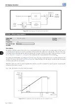
The CFW500 factory default settings define a linear relationship of the torque with the speed, overlapping points
P1, P2 and P3 at 50 Hz or 60 Hz; refer to the description of P0204. In this way, V/f curve is a straight line F defined
by just two points, P0136 which is the constant term or voltage in 0 Hz and the rated frequency and voltage
operation point (50 Hz or 60 Hz and 100 % of maximum output voltage).
The points
P
0
[P0136, 0 Hz],
P
1
[P0144, P0147],
P
2
[P0143, P0146],
P
3
[P0142, P0145] and
P
4
[100 %, P0134] can be
adjusted so that the voltage and frequency relationship imposed to the output approximates the ideal curve for the
load. Therefore, for loads in which the torque behavior is quadratic in relation to the speed, such as in centrifugal
pumps and fans, the points of the curve can be adjusted so energy saving is obtained.
NOTE!
A V/f quadratic curve can be approximated by: P0136 = 0; P0144 = 11.1 % and P0143 = 44.4 %.
NOTE!
If P0147 ≥ P0146 or P0146 ≥ P0145 or the V/f curve results in a segment with slope (rate) above
10 % / Hz, CONFIG (CONF) status is activated.
NOTE!
In frequencies below 0.1 Hz, the output PWM pulses are cut, except when the inverter is in DC
Braking mode.
Содержание CFW500 V1.8X
Страница 2: ......
Страница 4: ......
Страница 8: ...Contents...
Страница 34: ...General Information 2 4 CFW500...
Страница 38: ...About the CFW500 3 4 CFW500 3...
Страница 42: ...HMI and Basic Programming 4 4 CFW500 4...
Страница 52: ...Programming Basic Instructions 5 10 CFW500 5...
Страница 56: ...Identification of the Inverter Model and Accessories 6 4 CFW500 6...
Страница 76: ...Available Motor Control Types 8 4 CFW500 8...
Страница 84: ...V f Scalar Control 9 8 CFW500 9...
Страница 170: ...Communication 17 8 CFW500 17...