


Fault and Alarms
CFW500 | 15-3
15
0 60 120 180 240 300
3
2.5
2
1.5
1
0.5
0
Ou
tp
ut
c
ur
ren
t /
O
ver
lo
ad
c
ur
ren
t
Region of overload
Time(s)
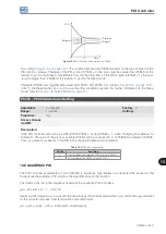
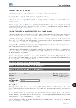
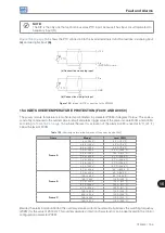
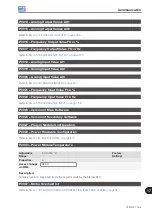
Figure 15.1:
Actuation of the motor overload
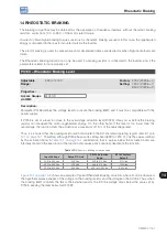
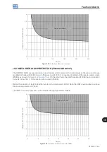
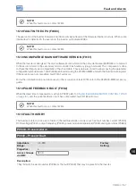
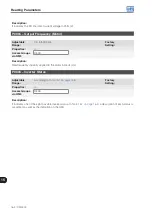
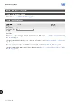
15.2 IGBTS OVERLOAD PROTECTION (F0048 AND A0047)
The CFW500 IGBTs overload protection uses the same motor protection format. However, the project point was
modified for the fault F0048 to occur in three seconds for 200 % of overload in relation to the inverter rated current
(P0295), as shown in
. On the other hand, the IGBTs overload (F0048) has no actuation
for levels below 150 % of the inverter rated current (P0295).
Before the actuation of fault F0048, the inverter can indicate alarm A0047 when the IGBTs overload level is above
the value programmed in P0349.
The IGBTs overload protection can be disabled through parameter P0343.
0 5 10 15 20 25 30
3
2.5
2
1.5
1
0.5
0
Ou
tp
ut
c
ur
ren
t /
O
ver
lo
ad
c
ur
ren
t
Region of overload
Time(s)
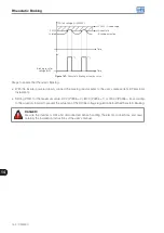
Figure 15.2:
Actuation of the overload of the IGBTs
Содержание CFW500 V1.8X
Страница 2: ......
Страница 4: ......
Страница 8: ...Contents...
Страница 34: ...General Information 2 4 CFW500...
Страница 38: ...About the CFW500 3 4 CFW500 3...
Страница 42: ...HMI and Basic Programming 4 4 CFW500 4...
Страница 52: ...Programming Basic Instructions 5 10 CFW500 5...
Страница 56: ...Identification of the Inverter Model and Accessories 6 4 CFW500 6...
Страница 76: ...Available Motor Control Types 8 4 CFW500 8...
Страница 84: ...V f Scalar Control 9 8 CFW500 9...
Страница 170: ...Communication 17 8 CFW500 17...