background image

Содержание WET6500A

Страница 1: ...bly Operation Maintenance Service and Adjustments Storage Troubleshooting Repair Parts For Parts and Service contact our authorized distributor call 1 800 849 1297 For Technical Assistance call 1 800 829 5886 WEED EATER 186100 Rev 1 02 21 03 TR PRINTED IN U S A ...

Страница 2: ...ing shut off the engine and makecertain all movingparts have stopped Disconnect the sparkplug wire and keep the wire away from the plugtoprevent accidental starting Disconnect the cord on electric motors Do not run the engine indoors exhaust fumes are dangerous Never operate the tiller without proper guards plates or other safety protective devices in place Keep children and pets away Do not overl...

Страница 3: ...our tiller Follow instructions under Maintenance and Storage sections of this Owner s Manual WARNING This unit is equipped with an internal combustion engine and should not be used on or near any unimproved forest covered brush covered or grass covered land un less the engine s exhaust system is equipped with a spark arrester meeting applicable local or state laws if any If a spark arrester is use...

Страница 4: ......

Страница 5: ......

Страница 6: ...VE TILLER FROM CRATE Make sure shift lever indicator is in N position See Fig 7 Tilt tiller forward by lifting handle Separate cardboard cover from leveling shield Rotate tiller handle to the right and pull tiller out of carton CHECKTIRE PRESSURE The tires on your unit were overinflated at the factory for shipping purposes Correct and equal tire pressure is important for best tillingperformance Re...

Страница 7: ...CONTROL CHOKE CONTROL DRIVE CONTROL BAR DEPTH STAKE LEVELING OUTER SIDE RECOIL STARTER HANDLE FIG 8 MEETS ANSI SAFETY REQUIREMENTS Our tillersconform to the safety standards of the American National Standards Institute THROTTLE CONTROL Used to control engine speed DRIVE CONTROL BAR Used to engage tiller DEPTH STAKE Controls depth at which tiller will dig LEVELING SHIELD Levels tilled soil OUTER SI...

Страница 8: ...e control bar and tiller will move forward REVERSE WHEELS ONLY TINES STOPPED DO NOT STAND DIRECTLY BEHIND TILLER Release the drive control bar Move throttle control to SLOW position Move shift lever indicator to R reverse position Hold drive control bar against the handle to start tiller movement HARD TO SHIFT GEARS Brieflyengage drivecontrol barand release or rocktiller forward and backward until...

Страница 9: ...h SAE 30 summer weight oil Be sure tiller is level and the area around oil fill is clean Check oil level before each use Add oil if needed Fill to full line on dipstick To read proper level tighten engine oil cap each time Reinstall engine oil cap and tighten For approximate capacity see PRODUCT SPECIFIC ATIONS on page 3 of this manual All oil must meet A RI Service Classification SF SJ For cold w...

Страница 10: ...ttle in stow position mid way between FAST and IDLE Tilling is digging into turning over and breaking up packed soil before planting Loose unpacked soilhelps root growth Best tilling depth is 4 to 6 10 15 cm A tiller will also clear the soil of unwanted vegetation The decomposition of this vegetable matter enriches the soil Depending on the climate rainfall and wind it may be advisable to till the...

Страница 11: ...o 3 2 5 7 5 cm Lower the outer side shields to protect small plants from being buried Cultivate up and down the rows at a speed which will allow tines to uproot weeds and leave the ground in rough condition promoting no further growth of weeds and grass See Fig 15 FIG 15 ADJUST WHEELS FOR CULTIVATING See Figs 16 and 17 Place blocks under righthand side of tillerand remove hairpin clip and clevis p...

Страница 12: ...warranty the operator must maintain tiller as instructed in this manual Some adjustments will need to be made periodically to properly maintain your tiller All adjustments in the Service and Adjustments section of this manual should be checked at least once each season Once a year you should replace the spark plug clean or replace air filter and check tines and belts for wear A new spark PlUg and ...

Страница 13: ...iller is on level surface Oil will drain more freely when warm Use a funnel to prevent oil spill on tiller and catch oil in a suitable container Remove drain plug Tip tiller forward to drain oil After oil has drained completely replace oil drain plug and tighten securely Remove oil filler plug Be careful not to allow dirt to enter the engine Refillenginewith oiLSee CHECK ENGINE OIL LEVEl in the Op...

Страница 14: ...damaged SPARK PLUG Replace spark plugs at the beginning of each tilling sea son or after every 50 hours of use whichever comes first Spark plug type and gap setting is shown in PRODUCT SPECIFICATIONS on page 3 of this manual TRANSMISSION Once a season lubricate the right hand side gear case grease fitting with oz of EP 1 grease CLEANING Do not clean your tiller when the engine and transmission are...

Страница 15: ...itions Retighten handle lock lever securely after adjusting TIRE CARE I A CAUTION When mounting tires un less beads are seated overinflation can cause an explosion I Maintain 20 PSI 1 4 kg cm 2 of tire pressure If tire pressures are not equal tiller will pull to one side Keep tires free of gasoline or oil which can damage rubber HANDLE HIGH HANDLE LOCK LEVER HANDLE LOW POSITION FIG 22 TO REMOVE WH...

Страница 16: ...ecked for sharpness wear and bending particularly the tines which are next to the transmission If the gap between the tines exceeds 3 1 2 inches 9 cm they should be replaced or straightened as necessary New tines should be assembled as shown in Fig 28 Sharpened tine edges will rotate rearward from above shred organic matter as effectively nor bury it as deeply as good tines A tine this worn needs ...

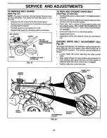
Страница 17: ...e from transmission pulley Place new belt in groove of transmission pulley and into engine pulley BELT MUST BE IN GROOVE ON TOP OF IDLER PULLEY NOTE POSITION OF BELT TO GUIDES Check belt adjustment as described below Replace belt guard Reposition wheel and replace clevis pin and hairpin clip GROUND DRIVE BELT ADJUSTMENT See Fig 28 For proper belt tension the extension spring should have about 5 8 ...

Страница 18: ...is position Tighten cable clamp screw securely THROTTLE CABLE SPEED STOP CABLI CLAMP SCREW LEVER FIG 29 TO ADJUST CARBURETOR Thecarburetorhas been preset atthefactoryand adjustment should not be necessary However engine performance can be affected by differences infuel temperature altitude or load If the carburetor does need adjustment contact your nearest authorized service center department IMPO...

Страница 19: ...mpty Neveruseengineorcarburetorcleanerproductsinthe fuel tank or permanent damage may occur Use fresh fuel next season NOTE Fuel stabilizer is an acceptable alternative in mini mizing the formation of fuel gum deposits during storage Add stabilizer to gasoline in fuel tank or storage container Always follow the mix ratio found on stabilizer container Run engine at least 10 minutes after adding sta...

Страница 20: ...n 3 Wait several minutes before attempting to start 4 Clean or replace air cleaner cartddge 5 Drain fuel tank and carburetor and refill tank with fresh gasoline 6 Remove fuel tank and clean 7 Make sure spark plug wire is seated properly on plug 8 Replace spark plug or adjust gap 9 Make necessary adjustments 1 Place throttle control in FAST position 2 Clean or replace air cleaner cartridge 3 Replac...

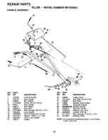
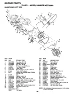
Страница 21: ... Rod Shift Bolt Carriage 3 8 16 x 1 Gr 5 Lock Handle Nut Crownlock 3 8 16 UNC Washer 13 32 x 1 x 11 Ga Lever Lock Handle Handle 20 19 KEY PART NO NO DESCRIPTION 26 159232 Cable Clutch 29 73731000 Nut Keps 10 24 UNC 31 150695 Bolt Pivot 34 145821 Bracket Clutch Cable 35 146480 Grommet Handle 36 180456X550 Bracket Handle 37 102604X Grip Bar Control 39 10040500 Washer Lock 5 18 38 73800500 Locknut 5 ...

Страница 22: ...5 16 18 x 3 8 Spacer Split 0 327 x 0 42 x 1 220 Washer 11 32 x 11 16 x 16 Ga Sheave Transmission Ring Retainer Spacer Split 0 327 x 0 42 x 2 09 Bolt Hex 5 16 24 x 1 2 Tire Rim Tire Valve KEY PART NO NO DESCRIPTION 24 126875X Rivet Drilled 25 4497H Clip Hairpin 26 165501X550 Guard Belt 27 132801 Belt V 28 104679X Pulley Idler 29 12000032 Ring Klip 30 159229 Bracket Idler 31 102384X Bolt Hex 5 16 16...

Страница 23: ...CRIPTION Bracket Reinforcement CounterWeight R H Washer Lock 3 8 Nut Hex 3 8 16 Bolt Hex 5 16 18 x 1 1 2 Clip Hairpin Rivet Drilled KEY PART NO NO DESCRIPTION 13 102190X Tire 183122X624 Rim 795R Tire Valve 14 73970500 Nut Hex Flange 15 Engine Tec Model No OHH65 Order parts from engine Manufac turer NOTE All component dimensions given in U S inches 1 inch 25 4 mm 23 ...

Страница 24: ......

Страница 25: ......

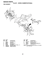
Страница 26: ...e Outer L H 8 74610616 Bolt Hex 3 8 24 x 1 2 132673 Clevis Pin 9 4460J Tine Outer R H 3 6554J Tine Inner LH 10 132728 Assembly Hub and Plate R H 4 3146R Clip Hairpin 11 6555J Tine Inner R H 5 132727 Assembly Hub and Plate LH NOTE All component dimensions given in U S inches 6 73610600 Nut Hex 3 8 24 1 inch 25 4 mm 7 10040600 Washer Lock 3 8 26 ...

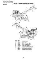
Страница 27: ...1 4 143678 5 141907 6 102180 9 141906 10 156199 12 162215 186100 186101 DESCRIPTION Decal Logo Decal Logo Decal Instruction Tilling Decal Hand Placement Decal Shift Indicator Decal Warning Rotating Tines Deal Reverse Decal Tine Shield Wrng Dom Manual Owner s English Manual Owner s Spanish 27 ...

Страница 28: ...rranty does not apply to any product which has been subjected to alteration misuse abuse improper assembly or installation delivery damage or to normal wear of the product 5 Exclusions Excluded from this Warranty are belts tines tine adapters normal wear normal adjustments stan dard hardware and normal maintenance 6 In the event you have a claim under this Warranty you must return the product to a...

Отзывы: