1
Remove Bucket if attached to the excavator dipper arm.
(8)*.
2
Install Quick Coupler using the carrier machine’s original dipper and linkage pins
(8, 9)*.
3
Once mounted, rotate coupler through its full range of movement and check clearances around
coupler and dipper arm
(9)*.
4
Begin routing hoses from coupler to the Hose Clamp Assembly on the dipper arm to determine
hose routing and Hose Clamp Bracket positioning
(10, 12)*.
5
Position dipper arm hoses, install hose clamps and connect hoses to the Hose Clamp Bracket as
labeled
(10, 12)*.
6
Position boom hoses, install hose clamps and join unions. Ensure all moving joints are fitted with
abrasive sleeve
(13)*.
7
After hose routing is completed, it will be easy to determine the best/final mounting location for the
coupler control valve
(11, 14)*.
8
Route hoses from valve ports to hoses on boom and join with unions
(14)*.
9
Locate and connect pressure line from test port on pump to “P” port on valve
(14)*.
10
Locate and connect hose from hydraulic tank return line to “T” port on valve
(14)*.
11
Locate mounting position for I-LOCK control switch in cab
(15)*.
12
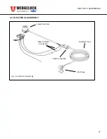
Route electrical harness from din connectors on valve to switch harness and attach positive and
negative leads
(15)*.
13
Check circuit pressures
(20)*
and test coupler function to ensure system is working properly
(refer to Operators Manual)
*(Refers to Installation Manual page reference)
I-LOCK
TM
MINI COUPLER
INSTALLATION REFERENCE CARD
PLEASE READ INSTALL MANUAL THOROUGHLY BEFORE INSTALLATION


