background image

-12 -  


Correct handling of the quick-release nut and balance shaft 


Note: Incorrect use of the quick-release nut or incorrect clamping and removal of 
the  wheel  can  damage  the  quick-release  nut  and  the  clamping  shaft.  The 
manufacturer/importer/seller  is  not  liable  for  damage  caused  by  improper  use. 
This damage is not covered by the warranty


Fastening and release of the wheel 

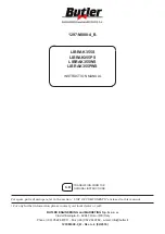
•  When installing and removing the wheel, guide the rim evenly to the centering cone without touching the 

clamping shaft as shown in Fig. 1. 

•  Slide the quick-release nut by operating the mechanism to the edge of the rim. Do not use the mechanism for 

tightening the quick-release nut but its handles. 


Fig. 1 Fastening the wheel 


•  Unscrew the quick-release nut until the rim is completely unscrewed, as shown in Fig. 2. Failure to do so may 

result in damage to the quick-release nut and the clamping shaft. 

•  When removing the wheel, take care not to damage the thread of the clamping shaft. Continue as shown in 

Fig. 1. 


 Fig. 2 


Quick-release 
mechanism 

Keep a distance! 

Содержание Klassik Series

Страница 1: ...ser s Manual Weber Klassik Series Wheel balancer Version 1 4 Status June 2016 www Weber Werke de Weber GmbH S lzbach 1 D 37293 Herleshausen Telephone 49 0 5654 343 Fax 49 0 5654 794 info Weber Werke d...

Страница 2: ...t and quick release nut 12 Working with the wheel balancer 13 Self Calibration 15 Balancing programs 16 Installation of the Motorcycle Clamping Axis Accessory 16 Troubleshooting 18 The information in...

Страница 3: ...liquid containers on the weight compartments or in the immediate vicinity of the display The machine must not be brought into contact with corrosive liquids and other substances that are harmful to i...

Страница 4: ...ood Wheel balancer mounted and fixed on a flat surface Electrical connection correctly established Wheel guard mounted Basic settings checked or changed Wheel balancer calibrated No defects have been...

Страница 5: ...the signatory this declaration shall lapse Description Wheel balancer Model Weber Klassik Serie wheel balancer manufacturer designation ZH825B Relevant EC Directives machinery guidelines 73 23 CEE 89...

Страница 6: ...Net weight kg 100 The use of all types of commercially available balancing weights is permitted Unpacking Unpack the device using the correct tools Pay particular attention to sensitive parts of the m...

Страница 7: ...y to anchor the wheel balancer to the floor Electrical connection The wheel balancer is designed to be connected to a standard 230 V 50 Hz socket The machine is equipped with a CE approved plug as sta...

Страница 8: ...crew the wheel guard together in the middle Fig 2 and click it on the corresponding frame Screw the wheel cover to the frame using the 2 screws provided 3 Place the wheel cover with frame on the conne...

Страница 9: ...imbalance value 2 Indicators for determining the internal imbalance position 3 Digital display for displaying the external imbalance value 4 Indicators for determining the external imbalance position...

Страница 10: ...diameter 7 Button for switching to the static balancing programme motorcycle balancing programme 8 Button for switching between ALU balancing programs 9 Button to switch to calibration mode 10 Button...

Страница 11: ...wheel onto the axle and center the hub hole of the rim with the cone on top Attach the wheel to the axle using the quick release nut Make sure that it is correctly centered Clamping method 2 clamping...

Страница 12: ...l guide the rim evenly to the centering cone without touching the clamping shaft as shown in Fig 1 Slide the quick release nut by operating the mechanism to the edge of the rim Do not use the mechanis...

Страница 13: ...rposition method is a commonly used clamping method Suitable for steel and alloy rims Press the selected cone onto the balancing flange Place the hub edge on the cone CAUTION The clamping shaft must n...

Страница 14: ...sitioning indicator Attach the counterweight to the inside of the rims in the 12 o clock position Continue turning the wheel until all LEDs on the right side of the positioning indicator light up cons...

Страница 15: ...rd or press the green start button The following figure appears after the wheel has been braked 4 Turn the wheel until all indicators on the right light up and a beep sounds Now clip on the supplied 1...

Страница 16: ...e rim ALU1 Balancing of alloy wheels with self adhesive weights on the shoulder of the rim ALU2 Balancing of alloy wheels with 2 adhesive weights on the inside ALU3 Balancing of light alloy wheels wit...

Страница 17: ...r incl wheel guard and balancing shaft Calibration weight rim width gauge weight rod weight rod 4 balancing cones quick release nut alloy rim adapter for quick release nut Installation and operating i...

Страница 18: ...supply 2 Replace the power supply 3 Replace the motherboard 2 Power supply defective 3 Defective motherboard Number of revolutions too low brake error inaccuracy in balancing Drive belt too loose Ope...

Отзывы:

Похожие инструкции для Klassik Series