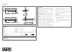
Typ
L
A
B
C
VLR 110
12.91
11.30
3.46
5.20
VLR 120
24.72
23.11
3.46
5.20
VLR 130
36.53
34.92
3.46
5.20
VLR 140
48.35
46.73
3.46
5.20
VLR 150
60.16
58.54
3.46
5.20
VLR 120 LA 24.72
23.11
16.69
18.43
VLR 130 LA 36.53
34.92
16.69
18.43
VLR 140 LA 48.35
46.73
16.69
18.43
Table 1
Installation Procedure
Luminaire is factory sealed and does not need to
be opened during installation.
1) Switch off the mains electrical supply.
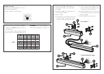
2) Determine position of the fixing screws
D
(not
included). Check
table 1
about the distance of
the drilling holes.
Drill corresponding fixing holes and insert dowel
E
(not included, choose suitable fixing material).
G
F
C
A
E
B
D
Remove foil befo
re use
L
N
PE
0–10 V +
0–10 V -
VLR110 Remote
3) Install wall bracket
B
to luminaire
A
and fix it
applying 2Nm (17.7in-lb) of pressure by use of
the screws
G
.
4) Install the luminaire
A
to the determined positi-
on by use of the screws
D
.
5) Connect cable
C
:
a) for the remote version (VLR110) the cable
C
of the gear box
F
is connected to the mains
supply in accordance with labelled cables.
b) for the integral version the cable
C
of the
luminaire is connected to the mains supply
in accordance with labelled cables.
6) After the luminaire
A
is connected, the bracket
can get adjusted by loosening and respectively
tightening screws
G
.
7) Remove film from the lens before use.
ATTENTION:
Make sure not to damage any
electrical cable, water pipes or other devices.
Remove foil be
fore use
L
N
PE
G
C
B
E
A
B
0–10 V +
0–10 V -
VLR120/130/140/150 Integral


