


Tele Indication, Type 10” Touch-V1
Index: 00
Date modified: 01/08/2017
OI No.: BA MR 002-00 Fernanzeige V1 EN.docx
Page 9 of 25
4.3
Mechanical installation
ATTENTION!
Ensure that the lines can move freely towards the back for installation and dismantling.
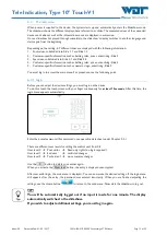
Install the remote display at the desired location:
1.
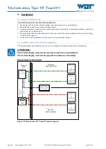
Make the wall cut-out (280x197mm) for the remote display according to the installation drawing.
Required installation space at least 60mm deep!
Installation drawing
Figure 4, Installation drawing
2.
Check if the installation frame (accessory) fits the cut-out.
Installation frame outside 333x250mm
Installation frame cut-out 260x177mm
3.
Mount the remote display on the installation frame using the clamping screws.
4.
Connect the remote display to the data cable (RJ45) and the power pack according to the illustration.
Figure 5, Rear of remote display with plug and power pack
5.
Check if the included SD card is inserted in the back of the remote display.
6.
Supply the power pack with voltage.
7.
Loosely attach the installation frame with remote display to the wall using 2 screws, since the SD card
must be removed for configuration.
Display
Wall
Wall cut-out
Wall
Frame
Frame


