background image

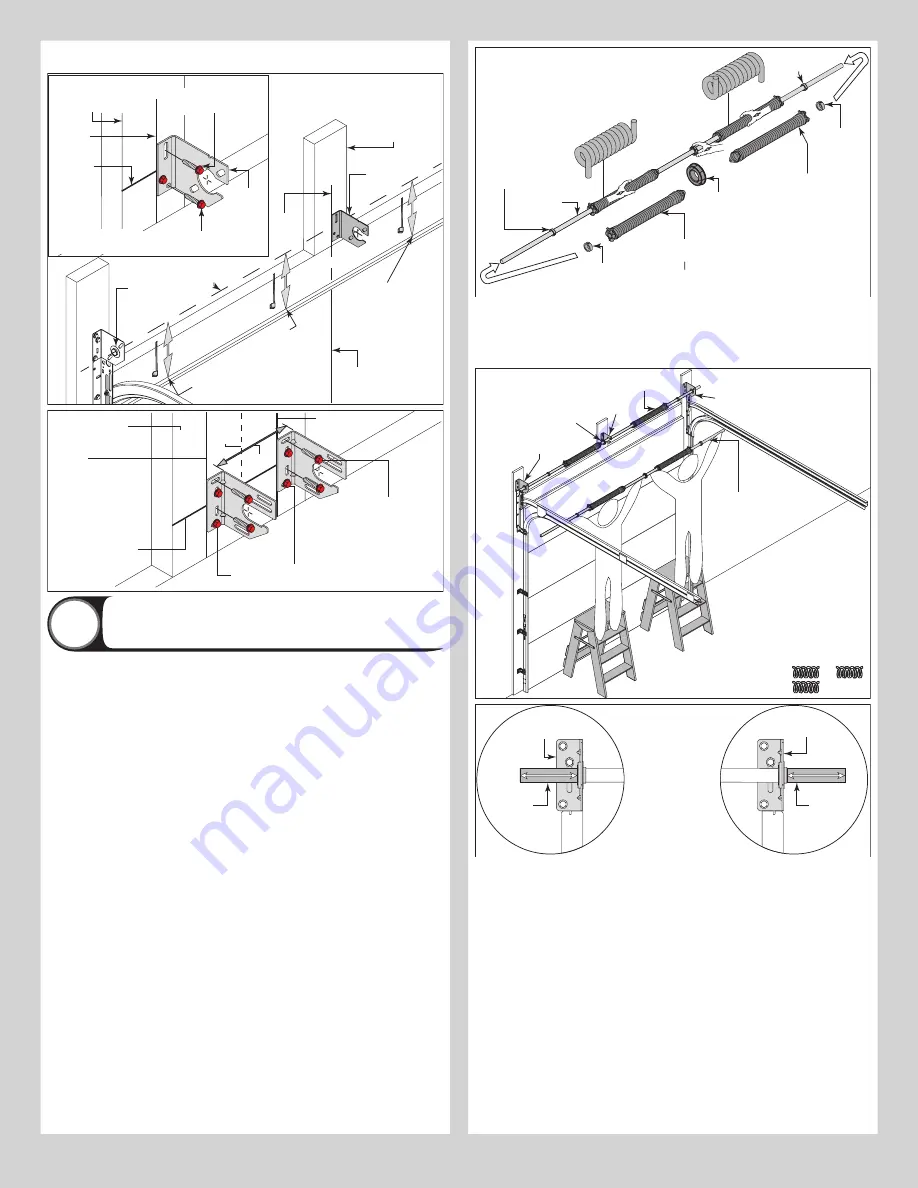
IF MOUNTING SURFACE IS A 2” X 6” BOARD INSTALLED ON TOP OF MASONRY, DRILL A 

CLEARANCE HOLE IN MASONRY FOR THE 5/16” X 2-1/2” RED HEAD LAG SCREWS.

Spring mounting 

pad (2” X 6”), White 

Pine or denser.

Typical 

center 

bracket

Vertical 

line

Equal distance (top of door 

section to horizontal line)

Horizontal 

line

Typical center 

of left hand 

end bearing 

bracket

Jamb

Equal distance (top of door 

section to horizontal line)

Center 

of door

Center 

bracket

5/16” x 1-5/8” Hex head 

lag screws (RED HEAD) 

Vertical 

line

Horizontal 

line

5/16” x 1-5/8” Hex head lag screw (RED HEAD) or 

5/16” x 2-1/2” Hex head lag screw (RED HEAD) 

Spring mounting 

pad (2” X 6”), White 

Pine or denser.

5/16” x 1-5/8” Hex head 

lag screws (RED HEAD) 

Vertical 

line

Mounting surface

(17” Minimum)

Horizontal 

line

Vertical line

† (2) Center bearing 

brackets spaced 6” to 

7” apart from the 

center of the door.

Center 

of 

door

†12”

5/16” x 1-5/8” Hex head lag screw (RED HEAD) or 

5/16” x 2-1/2” Hex head lag screw (RED HEAD)

Torsion Spring Assembly


18


NOTE:

 Refer to the Package Contents and or Parts Breakdown to determine if your door 

came with a coupler assembly.

IMPORTANT: 

RIGHT AND LEFT HAND IS ALWAYS DETERMINED FROM INSIDE THE BUILDING 

LOOKING OUT.

IMPORTANT: 

IDENTIFY THE TORSION SPRINGS PROVIDED AS EITHER RIGHT WOUND (RED 

WINDING CONE), WHICH GOES ON THE RIGHT HAND SIDE OR LEFT WOUND (BLACK WIND-

ING CONE), WHICH GOES ON THE LEFT HAND SIDE.

IMPORTANT: 

ON SINGLE SPRING APPLICATIONS, ONLY A LEFT WOUND (BLACK WINDING 

CONE), WHICH GOES ON THE LEFT HAND SIDE IS REQUIRED.

NOTE:

 The set screws used on all torsion winding cones and cable drums are colored red. 

DO NOT identify right and left hand by the set screw color.

IF YOU DON’T HAVE A COUPLER ASSEMBLY:

 Facing the inside of the door, lay the torsion 

shaft on the floor. Lay the torsion spring with the red winding cone at the right end of the 

torsion shaft. Lay the torsion spring with the black winding cone at the left end of the torsion 

shaft. Slide the center bracket bearing onto the torsion shaft followed by the torsion springs 

and set collars (if applicable).

IMPORTANT: 

THE CENTER BRACKET BEARING / TORSION SPRING(S) AND THE SET COL-

LARS (IF APPLICABLE) MUST BE POSITIONED, AS SHOWN.

Torsion 

shaft

Left wound, black winding 

cone (left hand side)

Right wound, red 

winding cone 

(right hand side)

IMPORTANT:

 ON SINGLE SPRING APPLICATIONS, ONLY 

A LEFT WOUND (BLACK WINDING CONE), IS REQUIRED.

NOTE:

 Layout counterbalance 

parts in proper orientation, then 

install onto torsion shaft, as shown.

Set collar (if 

applicable)

Set collar (if 

applicable)

Set collar (if 

applicable)

Set collar (if 

applicable)

Center 

bearing 

bracket

With assistance, pick up the torsion spring assembly and slide one end of the torsion shaft 

/ torsion keyed shaft through one end bearing bracket. Lay the middle of the torsion shaft / 

torsion keyed shaft into the center bracket. Slide the other end of the torsion shaft / torsion 

keyed shaft into the other end bearing bracket. Position the torsion shaft / torsion keyed shaft 

so that equal amounts of the shaft extend from each end bearing bracket.

Left 

hand 

end 

bearing 

bracket

Center 

bracket

Torsion spring 

assembly

Right hand end 

bearing bracket

Torsion spring 

assembly

Center 

bearing 

bracket

Or

Torsion 

shaft

Right hand end 

bearing bracket

NOTE:

 Position the 

torsion shaft so that 

equal amounts of the 

shaft extend from each 

end bearing bracket.

Torsion 

shaft

Left hand end 

bearing bracket

IF YOU HAVE A COUPLER ASSEMBLY:

 Disassemble the coupler assembly by removing the 

(3) 3/8” - 16 x 1-3/4” hex head screws and the (3) 3/8” - 16 nylon hex lock nuts from the 

coupler halves. Loosen the set screws. Set the components aside.

9

Содержание 8700

Страница 1: ...alton a division of Overhead Door Corporation Model 8700 T O R S I O N QUICK START GUIDE RESIDENTIAL AND LIGHT COMMERCIAL FRONT MOUNT LOW HEADROOM OUTSIDE HOOKUP DEFINITION OF LIGHT COMMERCIAL 1 Door...

Страница 2: ...It is recommended that 5 16 lag screws are pilot drilled using a 3 16 drill bit prior to fastening CAUTION IF ANY PART OF THE DOOR IS TO BE INSTALLED ONTO PRESERVATIVE TREATED WOOD PTFE COATED OR STAI...

Страница 3: ...weatherstrip with equally spaced nails Repeat for other side This will keep the bottom sec tion from falling out of the opening during installation Equally space nails approximately 12 to 18 apart 3...

Страница 4: ...earing Brackets As Required J4 Left Hand and Right Hand Cable Drums J5 Center Bracket As Required J6 Center Bracket Bushing As Required J7 Center Bearing Bracket As Required J8 Torsion Shaft Torsion K...

Страница 5: ...you don t have track roller carriers then skip this step Refer to Package Contents Breakdown Of Parts to determine if you have track roller carriers Starting on left hand side of the bottom section a...

Страница 6: ...n Enlarge the holes from outside the door to 1 2 diameter through the section Assemble the outside and inside lift handles to the section using 2 1 4 20 x 2 1 2 carriage bolts and 2 1 4 20 hex nuts an...

Страница 7: ...lace the bottom half inside the top half and flush against the inside surface of the top section Adjust both the top and bottom halves out as far apart as possible on the section surface Secure the dr...

Страница 8: ...ther side 3 8 16 Hex nut 3 8 16 x 3 4 Truss head bolt Upper slot 5 16 x 1 5 8 Lag screws Left end bearing bracket Horizontal track NOTE Repeat the same process for the right hand side Attaching Center...

Страница 9: ...he door lay the torsion shaft on the floor Lay the torsion spring with the red winding cone at the right end of the torsion shaft Lay the torsion spring with the black winding cone at the left end of...

Страница 10: ...er bracket Repeat the same process for the right hand torsion spring assembly Position both torsion keyed shafts so that equal amounts of the shafts extend from each end bearing brackets Torsion keyed...

Страница 11: ...til right and left cables both respond the same Once the counterbalance cables are set and if applicable tighten the coupler assembly together by tightening the 3 3 8 16 nylon hex lock nuts to secure...

Страница 12: ...door systems technician using proper tools and instructions DO NOT remove cover or paint over this tag Prod uct user should inspect this tag periodically for legibility and should order a replacement...

Страница 13: ...ack above third track roller Place locking pliers on torsion shaft as shown in D5 Insert a winding rod into the winding cone Push downward on the winding rod slightly while carefully loosening the set...

Страница 14: ...e top as less streaking will result Immediately following all washing operations thoroughly rinse the surface area with fresh water from a garden hose This cleaning and maintenance information is sugg...

Страница 15: ...oor is operated manually The adjacent bottom corner bracket and all cable retention features including milford pins cotter pins clevis pins are under HIGH SPRING TENSION Adjustments and repairs must o...

Страница 16: ...d object or exposure to toxic or abrasive environments including toxic chemicals or fumes and any fading or color change which may not be uniform due to unequal exposure of the curtains to sunlight or...

Страница 17: ......

Страница 18: ...rvice representative They will be happy to handle any questions that you may have Thank you for your purchase PLEASE DO NOT RETURN THIS PRODUCT TO THE STORE After installation is complete leave this I...

Отзывы: